Ok... I've been looking at different schematics of 6L6 UL amps and they all seem to use 12k to 24k feedback resistor value. The 10k listed for my amp is for EL34.
I've been told on this forum that using 6l6gc tubes you might benefit from a change in NF. I know from working on vintage guitar amps that less feedback often means better high end response.
I'd like to know what values to try...
The nfb resistor also depends on the input pentode's cathode resistor, which forms a voltage divider. Their ratio plus one sets the nfb gain.
Ok, if I aim for 10-20db range
What's the open loop gain of the amplifier?
I think I see........like for RF transfer the load is equal to the previous stage' s output impedance?
This is a just low pass filter. Whatever Thevenin equivalent resistance that the cable capacitance sees sets the hf roll off.
In this case, the Thevenin resistance value is the parallel combination of the preamp output resistance and the net input resistance of the amplifier.
So, the lower the input resistance of the amplifier, the wider the bandwidth. However, usually this is not important, because the source resistance
is typically very low, and the amplifier input resistance would have to be unreasonably low to make any difference in the bandwidth.
Last edited:
What's the open loop gain of the amplifier?
Errr.... I am sorry but Its all still new to me but trying to learn as much as possible... And yes, my dumb questions come with that ;-)
There are no dumb question's, we are all on here to learn and help each other.
In a very crude way that will roughly get you your answer just disconnect the feedback and measure the gain of the amp in db. Next close the feedback loop and measure the gain of the amp in db. Now subtract the closed loop from the open loop gain answers you got in db and that is how much feedback in db you have.
In a very crude way that will roughly get you your answer just disconnect the feedback and measure the gain of the amp in db. Next close the feedback loop and measure the gain of the amp in db. Now subtract the closed loop from the open loop gain answers you got in db and that is how much feedback in db you have.
This is a just low pass filter. Whatever Thevenin equivalent resistance that the cable capacitance sees sets the hf roll off.
In this case, the Thevenin resistance value is the parallel combination of the preamp output resistance and the net input resistance of the amplifier.
So, the lower the input resistance of the amplifier, the wider the bandwidth. However, usually this is not important, because the source resistance
is typically very low, and the amplifier input resistance would have to be unreasonably low to make any difference in the bandwidth.
OK thank you that makes sense, so the bandwidth increases but it pulls everything down.
OK thank you that makes sense, so the bandwidth increases but it pulls everything down.
Yes, that's right. In voltage amplifiers, we usually want high input impedance, to maximize voltage gain and minimize distortion.
Also we want usually want low output impedance, to maximize bandwidth.
Last edited:
what is the pot setting when you use your preamp?
if it is halfway up, measure the wiper to gnd and signal and then replace the pot with
2 resistors. In this case 10k and 10k giving the correct ratio and adding up to 20k
if it is halfway up, measure the wiper to gnd and signal and then replace the pot with
2 resistors. In this case 10k and 10k giving the correct ratio and adding up to 20k
Last edited:
No, nothing like that.famousmockingbird said:I think I see........like for RF transfer the load is equal to the previous stage' s output impedance?
The cable capacitance loads the source at HF and causes an HF droop. A low input impedance for the load loads the source at all frequencies so there is less droop because it is already lower at all frequencies. I am not recommending this as it results in signal attenuation and possible higher distortion. Just pointing out that the relevant resistance for calculating HF droop due to shunt capacitance is actually the parallel combination of source and load resistance.
The OPT may set the LF rolloff in some designs, but often NFB means that the OPT is asked to do things it cannot really do. If a coupling cap sets the rolloff then the OPT is relieved of this so it may generate less distortion.Wouldn't most output transformers do that anyway? I guess early in the chain would be better to maximize power efficiency.
Yes, feedback is usually set by the ratio of two resistors (although other circuit issues play a role - for example, the cathode impedance may appear in parallel with one of the resistors). Just saying that a feedback resistor is X k tells us nothing at all. Using dB is just a convenient way to talk about ratios, provided people understand logarithms and know what dB actually means.You can't just look at one resistor value because there needs to be another resistor to form the voltage divider. Usually when we speak of feedback we talk about it in db's.
Not quite. The cathode impedance appears in parallel with the grounded resistor. For a pentode this will be 1/gm.rayma said:The nfb resistor also depends on the input pentode's cathode resistor, which forms a voltage divider. Their ratio plus one sets the nfb gain.
Would people please note that 'dB' is the abbreviation for decibels.
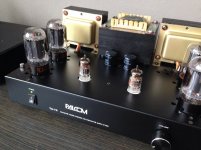
Working on a nice wooden trim for the front/sides. Power switch is gonna be move to the back and the volume knob gone since its no longer connected.
Been doing some more fiddling with the input inpedance.
On the scheme there's 470k + 20k pot. That gives 19.18K input balance.
My source is 2v @ 1k, meaning a signal loss from 2v to 1.9v at 19.18k input inpedance.
I replaced the resistors and put and went to 220k input indepance, which made the signal loss 2v to 1.99v
The amp does sound alot better. I know high input inpedance is better, is there a reason to go even higher?
Going from 1.9V to 1.99V is an increase of 0.4dB - so you won't hear it.
If the source has a non-linear output impedance then a lighter load will result in less distortion, but there is little point in going beyond a few hundred k - the source would have to be truly bad for this to give any significant advantage.
You are most likely hearing a slight change in frequency response. Our ears are quite sensitive to this, but our brains tend to assume that the result of any intended change is an improvement.
- Status
- Not open for further replies.
- Home
- Amplifiers
- Tubes / Valves
- Remove volume pot