Could this be the cause of an amp not working. I was looking at the bottom of the amp and saw that the solder on the ground terminal was melted and seem to have connected to the remote wire terminal.
{Using the word terminal as in the point where the wires go throught he board and are soldered in.}
Could this be the reason I am not gettin any output from the amp?
{Using the word terminal as in the point where the wires go throught he board and are soldered in.}
Could this be the reason I am not gettin any output from the amp?
Attachments
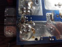
Yup.
Would also suspect that the head unit remote out is now shot.
They only use small surface mount transistors for these normally and just wont take any abuse.
What the helll did you do to heat that terminal up so much ???????
Extremely poor connection..
Would also suspect that the head unit remote out is now shot.
They only use small surface mount transistors for these normally and just wont take any abuse.
What the helll did you do to heat that terminal up so much ???????
Extremely poor connection..
Everything was installed professionally[4 years ago when i was 16 had no idea about nething], well originally. I have never touched the power and ground on this amp. I did change the outputs around, i wired down the subs to just under 1ohm, by accident that is. Theoretically it was 1 ohm but actually it was less. The amp was trying to draw too much current from my battery and caused it to overheat.
I actually thought i fried some mosfets, but everything seems normal.
And for the remote out from the head, its fine....but my stock infinity amp died as well. Thats my next project after i fix this.
I actually thought i fried some mosfets, but everything seems normal.
And for the remote out from the head, its fine....but my stock infinity amp died as well. Thats my next project after i fix this.
I no, i went from knowing nothing to starting my own small installation company. The only think i didn't think of, was that i should have checked everything with a multimeter to make sure resistance was correct.
This is the first time i actually tried to fix something inside an amp though. Im taking circuits in school and had some prof head me in the right dirrection. They were all more than willing to help because i was taking concepts from class beyond what i was taught.
Do you know if any amps have depleation mod mosfets.
Actually yes i think the remote wire does have a fuse, but it didn't fry. The hu was a pioneer avic-n2 navi. I installed it in my brothers car with 2 kicker l7s and everything works perfectly.
As far as I know, no amplifier uses depletion mode FETs to drive the transformer.
If you're reading anything near zero ohms between any of the terminals on any power supply FET, you could have any of the following:
1. The FETs are dead. If the short is between pin 1 and pin 2 of the FET, the FETs are almost certainly blown.
2. There's a short between power and ground (could be a solder bridge)
3. The reverse protection diode has shorted.
Well to mosfets that are reading 0 have a weird labling and i've been searching and can't find a replacement. they are labled: F15U200P 244
How else could there be a short?
Also where can i find the reverse protection diode, and what does it look like?
Thanks
How else could there be a short?
Also where can i find the reverse protection diode, and what does it look like?
Thanks
Not all amps have RP diodes. If yours has one, it's likely to be a standard cylindrical diode that's slightly larger than normal. It will be connected across the B+ and ground with the cathode (striped end) connected to the B+ terminal.
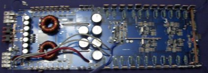
Can you post a good quality photo of the power supply from the top side of the board?
Have you pulled the FETs and checked them?
Can you post a good quality photo of the power supply from the top side of the board?
Have you pulled the FETs and checked them?
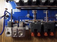
That's not the power supply. That's the power terminal block.
I would like to see the transformer, the FETS, inductors, capacitors, rectifiers... If you can't get good resolution in one photo, post an overall shot and then close-ups of the other components.
I would like to see the transformer, the FETS, inductors, capacitors, rectifiers... If you can't get good resolution in one photo, post an overall shot and then close-ups of the other components.
They are not FETs. They are likely rectifiers.
Do they have diode symbols on their face? Possibly all facing one direction?
Do they have diode symbols on their face? Possibly all facing one direction?
In order from left to right these are the lables
[1]
IFRZ48V
I[v]R 302H
34 B9
[v]= diode symble
[2]
F [lookes like manuf. symble]
F15U200P
244
[3]
TIP 36C
0 306
I thought that [2] were fets, and was going crazy looking for them online and came up with all dead ends.
So [1] are fets, what are [2] and [3]
[1]
IFRZ48V
I[v]R 302H
34 B9
[v]= diode symble
[2]
F [lookes like manuf. symble]
F15U200P
244
[3]
TIP 36C
0 306
I thought that [2] were fets, and was going crazy looking for them online and came up with all dead ends.
So [1] are fets, what are [2] and [3]
2 are likely rectifiers. If all 6 are the same, the internal diodes likely point the same way:
->|->|-
3 are the output transistors. There are likely TIP35Cs on the other side.
->|->|-
3 are the output transistors. There are likely TIP35Cs on the other side.
Yup i didn't realize they were different but they are.
And i found out that 2 are Fairchild rectifiers.
Know how could i possible check these w/o removing them from the board. Also what kind of charectaristics can i expect from them.
My prof told me to try and hook up the amp and test the AC thoughout the amp and try and find where it stops. the only place i think i could actually try that would be along the fets and rectifiers.
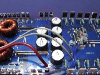
going by your last pic.
Left side will be switching mosfets (possibly irfz44) for the power supply.
Middle (circled) will be rectification and a pre regulator for power supply section.
Right side, output section. (amplifier)
Best way to test power faults in an amp is to remove the rectifier diodes, turn the on and measure (carefully) the votages where they came out.
one side will be -40volts (very rough guees depending on amp output) other side will be +40 volts.
to check the high speed diodes just a meter on its diode scale.
should get nothing one way and about .6 the other.
What do you mean turn them on? Turn on the rectifiers? Or did you mean the amp, and wouldn't it get damaged if the rectifiers weren't installed and power went through the board.
- Status
- Not open for further replies.
- Home
- General Interest
- Car Audio
- Remote wire grounded?