I have just taken delivery of a remote control kit based around the Atmel AT2313 and a ULN2803 transistor array.
I had anticipated building this into my preamp project, and using it primarily to control the volume - however I have run into difficulty...
I thought I would be able to drive the volume motor directly, but it seems that's not possible without some additional circuitry.
The kit has 2 'analogue' outputs which are essentially PWM outputs at around 8khz.
So, my rather ignorant question is..
How can I drive a motor (bidirectional for up and down control) from this PWM output?
I checked the output on my scope, and the mark space ratio varies when operating the "Volume" button on the remote.
I have Googled for a solution, but all the results I have seen so far, are purely PWM motor drive solutions, controlling only speed.
The ULN2803 can sink up to 800ma so drive current is not an issue for any proposed circuit.
Sadly, my knowledge of digital circuits is weak - I'm purely an analogue man at heart - so any assistance greatly appreciated.
TIA 🙂
So, a bit more research reveals that I need some kind of integrator, which can then produce a (H)igh or a (L)ow to drive an 'H' bridge which in turn drives the motor.
Perhaps I asked the question above without doing enough research 🙂
Perhaps I asked the question above without doing enough research 🙂
Its one of those things you need in front of you to play around with.
Is the output from the uP at a constant logic level when the keys are not pressed ? and does only one pin at a time generate this PWM signal. If so that should be easy enougy to detect and generate a logic 1/0 from to drive an H bridge.
Is the output from the uP at a constant logic level when the keys are not pressed ? and does only one pin at a time generate this PWM signal. If so that should be easy enougy to detect and generate a logic 1/0 from to drive an H bridge.
Help!
So it looks like I have an even bigger issue.
Turning the volume up and down changes the mark space ratio - so that's ok.
However....
If I use an integrator I will get a DC output, but only in one direction by the look of it.
The output direct from the Atmel also drives an LED indicator - so this is analogue. But the voltage is always there - i.e. it varies up and down, but doesn't drop to zero when the remote button is released.
So if I tried to drive it from that, the motor would just continue running, in whichever direction was previously selected.
Am I overlooking something here?
I can add some pics of the PWM scope waveforms if it helps?
Thanks.
What is the drive voltage for the volume control?
You would normally use 2 binary outputs from the controller to drive the motor, presuming a single speed of operation is satisfactory.
One output would drive the H-bridge for travel in one direction, the other, obviously the other direction. The H-bridge is simply a way to wire the motor so that independent drive can be applied to it in either direction. PWM would not be required,
w
I'll draw you a diagram if you need it. You don't need to use FETs, you can drive relays off the ULN2803.
Last edited:
As long as you can't drive 2 outputs simultaneously, this should be OK.

w
If you still want to make use of the PWM output, you can feed it into the relays to drive the motor, @8k the motor will accept it as readily as DC.
w
If you still want to make use of the PWM output, you can feed it into the relays to drive the motor, @8k the motor will accept it as readily as DC.
Last edited:
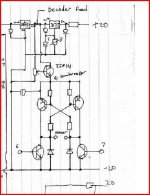
Transistor version here... this is part of a circuit I actually designed and built to add RC to my amp. As myself and Waki say, you normally need to outputs EITHER of which go high when volume up/down is pressed but NEVER together. The pot on the base of the TIP111 allows the motor speed to be set, something thats important to get the feel and usability correct of how fast the motor operates. Points 6 and 7 are the "logic" inputs to the bridge.
Attachments
Thanks guys.
I have concluded that I have one of two options.
I can either:
a) Reprogram the micro (that would be a steep learning curve!!)
b) Use the "Volume" (up) on the remote to turn it up, and the "Prog" (down) on the remote to turn it down.
This because it would appear that I only have a single output (for each remote function), which appears to be intended to control motor speed rather than direction.
Even the numbers on the remote are on/off toggles, meaning that you press a number, and an output is driven high, then press the number again and it goes low.
One other oddity I have noticed is the PWM output of the Volume and Prog controls.
If I have the motor connected to the output of the ULN2803... I press Volume UP, and the LED indicates a gradually rising drive voltage, but the motor doesn't move - then just around the point that the LED reaches maximum intensity, the motor begins to turn.
The motor I'm using is 5V, as is the drive from the ULN chip.
This is odd, because I would have expected a continuous analogue drive from the ULN, not so? (given that the input appears to be a continuously variable analogue drive)
Last edited:
This is absolutely brilliant and works exactly as described... just in case you go down another route with all this 🙂
FPRC5RX - DIY learning IR decoder
A PICKIT2 can programme the micro.
This was the module I used in my amp before I started playing around with the PICKIT,
http://www.antratek.ie/pdf/1_933.pdf
I have a feeling its not available now 🙁
FPRC5RX - DIY learning IR decoder
A PICKIT2 can programme the micro.
This was the module I used in my amp before I started playing around with the PICKIT,
http://www.antratek.ie/pdf/1_933.pdf
I have a feeling its not available now 🙁
This was the module I used in my amp before I started playing around with the PICKIT,
http://www.antratek.ie/pdf/1_933.pdf
I have a feeling its not available now 🙁
I just checked on the website, and was still able to add the item to a basket, so I presume it's still available.
Ironically, they're in Leeds (which is where I am...).
Thanks for this, although I may just embark on a crash course to learn about AVR programming!!
This is a bit of a sad story, as it seem that the device you have bought does decode IR remote commands, but it's outputs are configured to be close to useless for your purposes.
No, you can't. You could do this if you had some feedback from the pot as to it's position, which you could get if you connected a DC supply to it and read the wiper, but then you wouldn't have a volume control. You could then compare this voltage to the filtered PWM voltage and use the result to control a motor driver. This is how a servo works. You could actually do this by isolating the DC on the pot with caps, and thus separating it from the signal, but I hesitate to suggest this because it's not straightforward to arrange and there may be an impact on the sound. You're obviously out of your comfort zone already.
This is a bummer (disappointment). It's relatively easy to convert a momentary (short duration) switch output to a toggle, but it's impossible to convert the other way. While you could use a press to start the motor and another one to stop it, this is not ideal for small movements, and anyway it seems the system would allow you to command UP and DOWN simultaneously, which could be disastrous (on a small scale 😀).
The motor simply isn't getting over its starting inertia and friction in this case until nearly full voltage.
The input to the ULN should be PWM, not analogue. The effect is the same as continuously variable analogue because of the high switch rate and the capacitance or inductance in the driven circuit smoothing the output. The ULN should not be driven other than ON and OFF, because in these conditions the dissipation in it is minimal, if driven half-on the dissipation may exceed what is tolerable.
The drive from the ULN can be as much as 50V, if the COM input is supplied with it.
You really need to go with a different system, such as either of the ones suggested by Mooly.
w
I can...
b) Use the "Volume" (up) on the remote to turn it up, and the "Prog" (down) on the remote to turn it down.
This because it would appear that I only have a single output (for each remote function), which appears to be intended to control motor speed rather than direction.
No, you can't. You could do this if you had some feedback from the pot as to it's position, which you could get if you connected a DC supply to it and read the wiper, but then you wouldn't have a volume control. You could then compare this voltage to the filtered PWM voltage and use the result to control a motor driver. This is how a servo works. You could actually do this by isolating the DC on the pot with caps, and thus separating it from the signal, but I hesitate to suggest this because it's not straightforward to arrange and there may be an impact on the sound. You're obviously out of your comfort zone already.
Even the numbers on the remote are on/off toggles, meaning that you press a number, and an output is driven high, then press the number again and it goes low.
This is a bummer (disappointment). It's relatively easy to convert a momentary (short duration) switch output to a toggle, but it's impossible to convert the other way. While you could use a press to start the motor and another one to stop it, this is not ideal for small movements, and anyway it seems the system would allow you to command UP and DOWN simultaneously, which could be disastrous (on a small scale 😀).
One other oddity I have noticed is the PWM output of the Volume and Prog controls.
If I have the motor connected to the output of the ULN2803... I press Volume UP, and the LED indicates a gradually rising drive voltage, but the motor doesn't move - then just around the point that the LED reaches maximum intensity, the motor begins to turn.
The motor I'm using is 5V, as is the drive from the ULN chip.
This is odd, because I would have expected a continuous analogue drive from the ULN, not so? (given that the input appears to be a continuously variable analogue drive)
The motor simply isn't getting over its starting inertia and friction in this case until nearly full voltage.
The input to the ULN should be PWM, not analogue. The effect is the same as continuously variable analogue because of the high switch rate and the capacitance or inductance in the driven circuit smoothing the output. The ULN should not be driven other than ON and OFF, because in these conditions the dissipation in it is minimal, if driven half-on the dissipation may exceed what is tolerable.
The drive from the ULN can be as much as 50V, if the COM input is supplied with it.
You really need to go with a different system, such as either of the ones suggested by Mooly.
w
- Status
- Not open for further replies.
- Home
- Source & Line
- Digital Line Level
- Remote control based around Atmel ATtiny2313