Dear All,
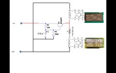
I’m struggling to get the circuit below working after making some updates. My main purpose is to have both relays switching after a delay. The delay has been build around a BC547C transistor and a small delay network.
The problem that I have is that only the Omron rely is switching, the Zettler is not working at all. When measuring the delay circuit it is working and supplying the 5V towards both relay coils.
I’ve been thinking about the current supplied by the BC547C, can it be that the current possible to flow is too limited to get both relays switching? As I’m using two different relays with slightly different coils the Omron works first.
Hope somebody can troubleshoot my diagram. Please forgive the simple way of drawing as I’m not educated in electronics but learning by doing and reading a lot on the internet.
Relay types are:
- Zetler AZ822–2C–5DSE
- Omron G5V-2-H1
Thx in advance!
Attachments
Why is the Omron relay 12V in the photo, and why does its coil have a series resistor?
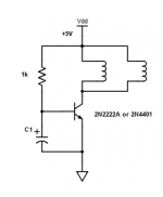
Have you tried a common emitter circuit, with the relay coils paralleled in the collector to +5V?
Have you tried a common emitter circuit, with the relay coils paralleled in the collector to +5V?
Last edited:
Strange circuit.
Why resistor in series with 12 volt relay ? should be a 5 volt relay and no resistor.
The circuit only puts out 4v3 to a 12 volt and a 5 volt relay.
No flywheel diode used so transistor will probably blow when relays turned off.
Why resistor in series with 12 volt relay ? should be a 5 volt relay and no resistor.
The circuit only puts out 4v3 to a 12 volt and a 5 volt relay.
No flywheel diode used so transistor will probably blow when relays turned off.
Thx for the quick reply,
The Omron is part of an existing circuit board and was supplied with 5V. The resistor was also in place towards the Omron, but I can remove it.
I'm adding the Zettler, which is 5V
The Omron is part of an existing circuit board and was supplied with 5V. The resistor was also in place towards the Omron, but I can remove it.
I'm adding the Zettler, which is 5V
Try a different circuit, as in post #2. Make sure there is sufficient base current to fully saturate the
transistor when on (timing resistor around 1k). A low leakage electrolytic capacitor is needed also,
with no shunting R across the cap.
transistor when on (timing resistor around 1k). A low leakage electrolytic capacitor is needed also,
with no shunting R across the cap.
Last edited:
The thing is that I cannot exchange the Omron relay, it is part of a complex circuit which I did not build and am not comfortable in soldering at.
If I understand correctly my coils are currently parallel.
So I should remove the resistor and use a different transistor. Which one should I use and can I just exchange it, or should I modify more to the circuit?
Thx for helping.
If I understand correctly my coils are currently parallel.
So I should remove the resistor and use a different transistor. Which one should I use and can I just exchange it, or should I modify more to the circuit?
Thx for helping.
The only reason to use the series resistor is if the supply were higher than 5V.
That may be the case on that board, check and see.
That may be the case on that board, check and see.
Ok, that is indeed not the case as only 5V is supplied.
It's late now, will short the resistor tomorrow to see what happens.
Thx!
It's late now, will short the resistor tomorrow to see what happens.
Thx!
Try this if possible. Might need a diode or two in series with the base.
Attachments
Last edited:
Make Q1 a darlington with a BD135/BD137?BD139 in a common emitter setup (post 2 & 6); lots of image search results available. From 5V with 3.3k resistor to 470µ parallel with the 100k. That node to the base of th BC547. Emiter of the BD13x to gnd, collector to both relays but do omit that 330Ω resistor (short it). Aadd two flyback diodes, one // to the relays, one // to the BD13x. The other legs of the relays to 5V.
The Zettler is a 5V relay and kicks in immidiately, the Omrom is a 12V type and may or not act, depending on its specs.
You can exchange the 5V supply for a 12V supply, but then add a series resistor to the Omron (approx 7V/20mA=330Ω).
Post me a pm for a simple drawing if needed.
When using a 555 circuit, time control is perfect and lots of fun:
555 Internals
edit: crossed with rayma above: that's the circuit (though I would add this 100k over C1)
The OP circuit is just a resistor divider with a big cap connected to an emitter follower. The base gets to about 3.75 V so the emitter goes to something closer to 3 V. This means the 5 V relay probably pulls in but the 12 V one has no chance.
Don't worry about the freewheel diode, the emitter voltage changes so slowly there's no kickback to deal with.
tommost
Don't worry about the freewheel diode, the emitter voltage changes so slowly there's no kickback to deal with.
tommost
Made the trial tonight and removed R3 from my circuit. It indeed makes a difference!
Now both relays are working. The only strange thing is that the second relay (the Zettler) is switching a lot later than the Omron (previously the only one working).
The total time delay to the omron is around 18 seconds,
Now both relays are working. The only strange thing is that the second relay (the Zettler) is switching a lot later than the Omron (previously the only one working).
The total time delay to the omron is around 18 seconds,
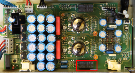
I measured and the voltage going to the Relay coils is rising slowly to a maximum of only 2 Volts.
So indeed I'm having low voltage to drive the coils. The strange thing however is that the Omron or 12V relay is engaged first. I think that this might be due to other circuitry on the board I'm connecting to. The picture shows the relay on the board.
To give background, this is the original post with the design I'm now tweaking.
How to build a Digital input on a Njoe Tjoeb 400 (Marantz CD 4000) cd player.
i added the second relay with the idea to drive a dual led for indication of power with a warm up time for the tubes. So switch from red to green.
Attachments
@ MorbidFractal,
This indeed is more difficult setup, not sure if I fully understand it. You add on both line and ground a double delay?
This indeed is more difficult setup, not sure if I fully understand it. You add on both line and ground a double delay?
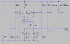
Sorry. Some words. It is in effect a discrete comparator.
Q1 and Q2 form a differential, long tail, pair. R2 sets the tail current. Ignoring D1 and D2 R3 and R11 would set the base of Q2 at about 7.5V, half the 15V supply. At power on C1 is discharged, 0V. It charges via R1, this is your single time constant. While the base of Q1 is below that of Q2 Q1 is on and the tail current from R2 passes through Q1 to ground. When the base of Q1 rises above about 7.5V Q1 turns off and Q2 turns on with the tail current passing through Q2 via R6 and R7 to turn on Q3 and Q4, R9 and R10 provide for turn off of Q3 and Q4. The collectors of Q3 and Q4 are used to provide independent drives, open collector, to your relays. R4 and R5 are not necessary. D3 and D4 clamp turn off spikes from the relay coils, they are inductive loads and without the, clamp, diodes would be unclamped inductive loads. D1 and D2 protect Q1 and Q2 against reverse base emitter voltages but also have the effect that R3 will contribute to the charging current of C1 via D1 when it is forward biased. This will change the apparent time constant of the circuit.
Q1 and Q2 form a differential, long tail, pair. R2 sets the tail current. Ignoring D1 and D2 R3 and R11 would set the base of Q2 at about 7.5V, half the 15V supply. At power on C1 is discharged, 0V. It charges via R1, this is your single time constant. While the base of Q1 is below that of Q2 Q1 is on and the tail current from R2 passes through Q1 to ground. When the base of Q1 rises above about 7.5V Q1 turns off and Q2 turns on with the tail current passing through Q2 via R6 and R7 to turn on Q3 and Q4, R9 and R10 provide for turn off of Q3 and Q4. The collectors of Q3 and Q4 are used to provide independent drives, open collector, to your relays. R4 and R5 are not necessary. D3 and D4 clamp turn off spikes from the relay coils, they are inductive loads and without the, clamp, diodes would be unclamped inductive loads. D1 and D2 protect Q1 and Q2 against reverse base emitter voltages but also have the effect that R3 will contribute to the charging current of C1 via D1 when it is forward biased. This will change the apparent time constant of the circuit.
- Home
- Amplifiers
- Power Supplies
- Relays with delay