rpapps said:Hi Jarthel
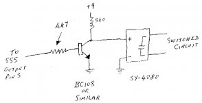
At the risk of throwing in another confusion factor, how about something like this.
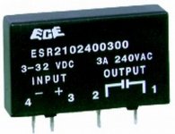
It's an SY-4080 from Jaycar Electronics.
do you think it would work with the ne555 circuit above?

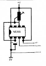
using a mechanical relay, one side of the coil is connected to the reset of the ne555 (pin8) and the other side is connected to trigger (pin7)
with your changes, what happens to these connections?
with your changes, what happens to these connections?
Hi
The relay is actually connected to pin 3 (output) and pin 4 which is connected to the + supply. Neither of the two diodes shown would be needed. My mod would take its input from pin 3 and its + and ground connections from the equivalent pins on the 555.
Cheers
Rob
The relay is actually connected to pin 3 (output) and pin 4 which is connected to the + supply. Neither of the two diodes shown would be needed. My mod would take its input from pin 3 and its + and ground connections from the equivalent pins on the 555.
Cheers
Rob
rpapps said:ground connections from the equivalent pins on the 555.
Cheers
Rob
do you mean power supply ground? cause the only ground connection of the 555 is connected to power supply ground.
should it look like something like this? :
An externally hosted image should be here but it was not working when we last tested it.
rpapps said:Hi
Yes that's right.
I simplified the circuit a bit.
Cheers
Rob
I assume the "reset" pin of the n3555 is not needed anymore?
rpapps said:Yes it is. Just leave it connected to the + supply as shown in your original circuit.
thank you very much. looking for a relay that will work in either 9 or 10V is so hard in this country! :| even when looking at RS
rpapps said:Hi Jarthel
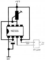
I thought about it some more and it can be done more simply.
Cheers
Rob
any reason for the change? also, why is the "-" pin of the relay on the trigger? (i think it's the trigger)
thanks again
...instead of inverting the state of the output of the 555, couldn't you just "tug" on the low side of the SS relay's LED?? and have the Hi side pulled up to supply
....oops, I saw above post . Sorry for being late

....oops, I saw above post . Sorry for being late
Hi Jarthel
Reason for change is just to make it simpler - fewer parts, easier to make. I should have thought of it earlier but I'm >57 and not as quick as I used to be.
The + of the relay goes to + supply via the current limiting resistor and the - of the relay is pulled to ground by the 555 output. It's just another way of defurring a feline.
Cheers
Rob
- Status
- Not open for further replies.
- Home
- Design & Build
- Parts
- relay voltage rating