There's no telling without schematics and possibly captured waveforms. Most non-trivial circuits have various time constants designed into the different sections. Not all designers have Power Loss Behavior on their list of things to work out.
Though not all power supplies fade gracefully, they are notably less likely to be the exact culprit than the powered circuit.
A buddy and I each bought an equalizer from the same manufacturer in the mid '70s. His was supposed to be the 'improved' version of mine and employed the 'new' monolithic regulators; it generated a huge thump On and Off. Mine instead had 5W zeners and never made a peep, On or Off! But that's one of the few instances I know of that the power supply definitely played a role.
I really feel for you guys that have unreliable power -- that has to be a recurring nightmare. Maybe a modest UPS would be a worthwhile investment.
Cheers
You also have to consider that it is maybe not just the power failure but also the power coming up again. If you also have the bang at that point, your circuit will not be active at that point.My audio chain consists of a USB DAC -> Active Filter -> Amplifiers -> Speakers.
There are frequent power failures, that result in a loud bang that could potentially damage my ears and the speakers. I suspect that the USB DAC is the culprit. The USB DAC is powered by a 5V linear PS.
I was wondering if a relay to short out the outputs of the USB DAC on a power failure would limit the damage. I can introduce a 100 ohm resistor in the shorted paths to limit the output current.
The 5V relay I am considering is the Omron G5V-1 (5V, 30 ma, 176 ohms).
Can you please review my scheme and suggest improvements? The zener diode will be 3.6V in the implementation.
Thanks
Jan
Please review if this scheme will work for me on a power down situation, and help me understand limitations:
Use a "low level trigger" SSR module like this one. My understanding is that on a low trigger voltage (< 0.5V DC), the relay state is ON.
In the ON state, I can shunt the amplifier output to a power resistor (around 2 ohms, 10W).
In this scheme there should be no degradation of the output, when power is on, right?
On startup, I will ensure that the relay unit is switched on last.
I am only concerned by the voltage drop in the ON state for the Omron SSR (around 1.6V). Can't figure out the corresponding ON resistance, or if this will derail my approach?
Thanks
I think there are multiple issues in my earlier post. Please ignore.Please review if this scheme will work for me on a power down situation, and help me understand limitations:
Use a "low level trigger" SSR module like this one. My understanding is that on a low trigger voltage (< 0.5V DC), the relay state is ON.
In the ON state, I can shunt the amplifier output to a power resistor (around 2 ohms, 10W).
In this scheme there should be no degradation of the output, when power is on, right?
On startup, I will ensure that the relay unit is switched on last.
I am only concerned by the voltage drop in the ON state for the Omron SSR (around 1.6V). Can't figure out the corresponding ON resistance, or if this will derail my approach?
Thanks
As far as the speed issue, I was thinking of a SSR. but it is backwards. We need NC contacts.
I am battling various thumps on power loss. I use a sequencer for power on and off, and amp has a muting relay, but still stuff gets through. My analog crossover is the worst as it is a single supply with artificial ground so the rails do not come up symmetrically. Not sure my sequencer ( Pyle) has caps across the coils.
I am battling various thumps on power loss. I use a sequencer for power on and off, and amp has a muting relay, but still stuff gets through. My analog crossover is the worst as it is a single supply with artificial ground so the rails do not come up symmetrically. Not sure my sequencer ( Pyle) has caps across the coils.
I designed an amp protection systems using mosfet SSR outputs.
I used a little PIC micro to sense power and power down.
If AC out of power transformer failed it immediately turned off SSR
It also detected DC on output.
I used a little PIC micro to sense power and power down.
If AC out of power transformer failed it immediately turned off SSR
It also detected DC on output.
Inspired by the SSR ideas and implementations discussed in this thread, I am thinking of a an approach using a simple PC817A optocoupler.
This is a SSR shunt, to activate on a power loss. The AC loss detector is from ESP (Rod Elliot). Assuming the Mosfet Vgs threshold is > 2V.
My question is: is the PC817A able to drive the Mosfet gates, and quickly?
Please take a look at the simulation files, and let me know if this can fly.
This is a SSR shunt, to activate on a power loss. The AC loss detector is from ESP (Rod Elliot). Assuming the Mosfet Vgs threshold is > 2V.
My question is: is the PC817A able to drive the Mosfet gates, and quickly?
Please take a look at the simulation files, and let me know if this can fly.
Attachments

To address the speed issue, you can reduce the resistance level of the detector, in particular R4.
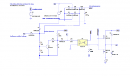
I see a potential issue: the gate drive is self-biasing thanks to the output signal. I think this is unhealthy: for example, the opto will see the full output swing when off, + the auxiliary supply voltage.
The gate supply should be fully isolated and floating.
It is possible to improve the reaction speed by using a full wave detection: either add D9, or remove D1 and use D10 to isolate the filter cap.
The picture shows both options:
Attachments
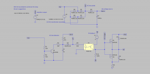
You also need to take the transfer ratio of the opto into account.
This variant takes it into account, and makes good use of the full-wave configuration advantage:

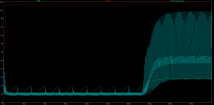
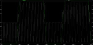
If you really intend to use a 9V battery as a floating supply, it would be preferable to use a totem-pole drive: the static consumption is ~=0, and the switching is much faster and cleaner.
In those conditions, the battery life will be its shelf-life:

As you can see, the reaction is almost instantaneous
This variant takes it into account, and makes good use of the full-wave configuration advantage:
If you really intend to use a 9V battery as a floating supply, it would be preferable to use a totem-pole drive: the static consumption is ~=0, and the switching is much faster and cleaner.
In those conditions, the battery life will be its shelf-life:
As you can see, the reaction is almost instantaneous
Attachments

Thanks Elvee, for the brilliant design (as always). Need to read up on the totem pole driver, and how the trigger became almost instantaneous.
Looks like there is minimal current consumption from vplus and the battery. Now, can this approach be extended to three output relays (for three amplifier channels)? Any optimisations to reduce the number of the isolators?
I am planning a separate unit to house this functionality, separate from the amplifiers.
Attached my latest .asc file for records.
Attachments
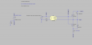
The drive current is much higher, and active for both polarities unlike a passive pull-upThanks Elvee, for the brilliant design (as always). Need to read up on the totem pole driver, and how the trigger became almost instantaneous.
If you use multiple channels, you will need a separate floating supply for each one. You could use three tiny lithium button cells in series for each channel: their life will be almost infinite.Looks like there is minimal current consumption from vplus and the battery. Now, can this approach be extended to three output relays (for three amplifier channels)? Any optimisations to reduce the number of the isolators?
I am planning a separate unit to house this functionality, separate from the amplifiers.
Another possibility is to use a micro-converter like these: https://www.diyaudio.com/community/threads/symetrical-colpitts-oscillators.329968/post-5601529 with as many secondaries as you need. The current consumption is ridiculous, and thanks to the sinewave operation, high frquency and low capacitances, the disturbances are minimal.
Note that the current consumption on V+ is not zero, it is determined by the number of 1K resistors feeding the opto's.
Optocouplers come in handy dual channel version (or even 4 channels) if you want to rationalize the build.
This may do the trick. I plug my whole power strip into one of these. Trips and requires you to reset.
Manual Reset GFCI
Manual Reset GFCI
Hi Elvee,
Continuing the private conversation, any thoughts on using dc-dc isolated converters? Are they viable? They could be driven off of the vplus source. With 3 dc-dc converters, we can get 3 separate isolated and floating supplies? Thoughts?
Rod Elliot has a similar scheme to trigger mosfet relays.
Continuing the private conversation, any thoughts on using dc-dc isolated converters? Are they viable? They could be driven off of the vplus source. With 3 dc-dc converters, we can get 3 separate isolated and floating supplies? Thoughts?
Rod Elliot has a similar scheme to trigger mosfet relays.
In theory, yes, but DC-DC converters are vast overkill for such an application (they rarely come in power <0.5W), and they are noisy, especially the cheap ones. They generate perturbations, especially common-mode ones, and they radiate magnetic and electrostatic fields.
This is why I suggested a sinewave oscillator, but it needs some personal work.
Another attractive solution is a photovoltaic coupler: it is completely static and silent, compact, and the power level is well-suited to this type of application
This is why I suggested a sinewave oscillator, but it needs some personal work.
Another attractive solution is a photovoltaic coupler: it is completely static and silent, compact, and the power level is well-suited to this type of application
I tried simulating the TLP3906, using the model provided by Toshiba. I can't understand what's happening here, as the Mosfets are conducting when they shouldn't. The input current in the photo coupler is 11mA.
Can you please take a look and debug? Is the model suspect, or am I missing something?
Thanks
noticed the typo tlp3096, sorry about that
Can you please take a look and debug? Is the model suspect, or am I missing something?
Thanks
noticed the typo tlp3096, sorry about that
Attachments
The model may have issues, but anyway the coupler shouldn't drive the MOSfets directly. There are application notes about the subject (to get a clean switching action, etc.).
It will be complicated to combine that with a fast power failure protection.
I recommend you just use the TLP as a floating supply, with a good bypass capacitor, like 47µ
It will be complicated to combine that with a fast power failure protection.
I recommend you just use the TLP as a floating supply, with a good bypass capacitor, like 47µ
Attachments
I'm seeing a lot of designs in the earlier parts of this topic that rely on the supply voltage that powers the relays to be the one that collapses. But now I'm thinking, why is that necessary? Why complicate your own situation by introducing a race for time?
Simply sensing the AC dropping out could act as a trigger, and if you're fine with a little bit of power loss, an opto can be put directly on mains with a resistor of suitable size, as far as I know, that's how many HVAC systems do their MainsPresence sensing, albeit higher power transistors used. It is more expensive, but often worth the solid performance and predictable turn off time for relatively low power systems (eg, not huge power amps.)
On topic of the last posts, I agree with Elvee. Just use the TLP as it was mostly intended to be used. Using it in any odd less common configuration is likely to cause these weird behaviours to pop up.
Hi Elvee,
Lots of people have successfully implemented opto based SSRs with the opto driving the Mosfets directly, and one is right here.
I read the Toshiba design guide, and it mentions a similar scheme (opto driving the Mosfets directly) with no caveats.
If you notice, the Mosfets conduct during the negative cycle of the amp signal.
I also noticed that the earlier circuit I posted, behaves well with small magnitudes of the amp signal. It gets worse as the amp signal increases. Are we hitting some limits of the photo diode voltages? The maximum reverse voltage on the output photo diode is listed as 10V.
Just wanted to understand what's going on.
- Home
- Amplifiers
- Power Supplies
- Relay protection on power failure