I am trying to switch on a source selector relay board using Arduino. The source selector has 12v relays with common ground and +12v are separate for the 5 relays ( I wish it were the other way around). Can I use the circuit below to switch the 12v relays ? Any suggestions?
Thanks,
Dinesh
Thanks,
Dinesh
Attachments
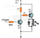
The input base resistor should be 24k or less to ensure the saturation of the BC547, if the input is 3.3V.
If the input is 5V, the base resistor should be less than 39k.
What is the rated relay coil current?
If the input is 5V, the base resistor should be less than 39k.
What is the rated relay coil current?
Last edited:
Its a 12v relay with 1028ohm coil resistance. Also I was planning to use BC549/559 transistors. I have 5v at the base, and will 34k base resistor be sufficient or does it have to be 39k?
Thanks
Thanks
.... I have 5v at the base, and will 34k base resistor be sufficient or does it have to be 39k?
...24k or less ...if the input is 3.3V. ....5V, ....less than 39k....
34k is "less than" 39K and is OK.
1k or less would be very wasteful of current and heat, but 34k is nowhere near there.
The coil current is 0.0116A
Thanks
That will work fine. For the BC557 base resistor, up to 7.2k will work fine instead of the 1k.
So up to 39k base resistor for the first transistor, and up to 7.2k for the second base resistor.
The two values don't interact significantly.
Last edited:
Its a 12v relay with 1028ohm coil resistance. Also I was planning to use BC549/559 transistors.
I have 5v at the base, and will 34k base resistor be sufficient or does it have to be 39k?
Thanks
Either is ok, since 39k is the maximum value that will work with all input transistors.
Lower value is ok, but not necessary. You just need enough base current to saturate the
input transistor under all conditions and in all cases. Same for the second transistor.
If either resistor is too high in value, the associated transistor may not saturate fully (or at all),
and then the relay wouldn't switch.
Last edited:
Either is ok, since 39k is the maximum value that will work with all transistors.
Lower is ok, but not necessary. You need enough base current to saturate the
input transistor under all conditions and in all cases. Same for the second transistor.
thanks for your help Rayma.
Mention if it works ok now.
It's odd they insist on grounding one end of all the relay coils.
Normally they would all go to the positive rail, not ground.
It's odd they insist on grounding one end of all the relay coils.
Normally they would all go to the positive rail, not ground.
Last edited:
Folks,
I would like to a question of understanding:
(Why) Are two transistors really needed here to drive the relay?
To my understanding the one NPN transistor would/should be able drive sufficient current through the coil even if its current amplification hfe is only 100...200: 12mA/hfe=120...60µA to be drawn from the source. What am I missing (probably something basic 🙄) ?
Thanks and regards,
Winfried
You're right, but here the coil is connected to ground, not the positive rail.
Since the control signal is also ground referenced, you need two stages, not one.
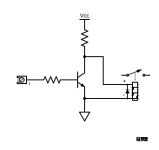
There actually is a tricky way to just use one transistor with a coil that is ground referenced,
but then a high input means that the coil is off (the opposite of the circuit with two stages,
as you would expect).
Since the control signal is also ground referenced, you need two stages, not one.
There actually is a tricky way to just use one transistor with a coil that is ground referenced,
but then a high input means that the coil is off (the opposite of the circuit with two stages,
as you would expect).
Attachments
Last edited:
Thanks for stating the obvious 😀 I had overlooked the "common ground for all relays" bit, just looked at the schematic.
The relay "shunting" circuit looks funny to me
Greetings,
Winfried
The relay "shunting" circuit looks funny to me
Greetings,
Winfried
- Home
- Design & Build
- Construction Tips
- Relay driving circuit for switching 12v