Higher voltage relays draw less current through their coils.
That reduces the requirement for base current into Q2. That in turn reduces the current through and into Q1, leaves the possibility to use the 470k and still get enough to turn on Q1.
If you add a green LED between Q1 emitter and Q2 base you have an indicator for good to go.
And it allows a much smaller capacitor for the timing. Maybe even an MKT with near zero leakage for consistent timing.
And if you use 18V regulator to supply this circuit you can incorporate a current saver with clean DC so you don't have interference near the signal contacts. I consider the advantage of going to 18Vdc as too strong to ignore.
BTW Mooly.
If I'm going to use your circuit for higher voltage eg. 12V or 18V should I change something? OFC I know I should replace cap for higher voltage rating and relay 😉
But should I change something more?
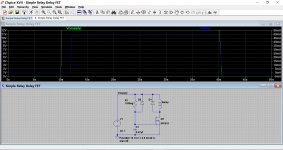
Here is a FET version for 9 volt and higher supplies. Notice the value of the cap and resistor now.
Attachments
The Apt Holman preamp (from the 70s) does this. Schematics and explanations are available freely online. I'm not saying it's the best way to implement it, but it's always educational to see different solutions.
Here is a FET version for 9 volt and higher supplies. Notice the value of the cap and resistor now.
I'll apologize for my noobishness but...
I have a question about this schematic. I have a 12v relay. In my DAC/preamp I have 12VDC available from de DAC board, and from the transformer I have 9VAC and 15VAC available. Which one should I use to power this circuit? My relay has a pick up voltage of 9VDC and a max voltage of 24VDC
Regulated 12VDC seems to me like the obvious choice but I am confused why it says AC in the schematic.
On the other hand If I grab 15V from the transformer, the relay might have a faster response time...
The circuit itself must run on DC.
The reason it says AC on the simulation is because the voltage source has to start at 0 and then rise to 12 volts to simulate the power being applied, and then it falls to zero as power is removed. So in simulation language that is AC signal 🙂
If you power the circuit from an existing 12 volts DC rail then the relay drop out time will depend on how quickly the 12 volt rail collapses at power off.
If you use the AC winding then you must also add a rectifier (one diode) and a small reservoir cap. In many ways that is a better solution because you are powering the circuit from its own independent supply and so can tailor the drop out time to suit. The reservoir cap would be very small, perhaps just 47uF.
If you are interested in doing it that way then I can probably simulate that for you.
I have a 9v winding available which should give me just about 12v rectified. Will this work?
Also my local shop did not have the 2n7000 so they gave me bs170.
Also if I use a 1M resistor and a 4,7uF capacitor, will the delay time stay the same? That is what I have in stock right now
Also my local shop did not have the 2n7000 so they gave me bs170.
Also if I use a 1M resistor and a 4,7uF capacitor, will the delay time stay the same? That is what I have in stock right now
Attachments

Last edited:
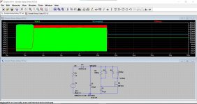
1 Meg and 4.7uF would give the same time constant but if the 4.7uF is an electrolytic then its leakage current is rather more significant. Try it.
We can just use a single half wave rectifier rather than a bridge, it simplifies things.
The additional low value resistor I've added is good practice and greatly eases the stress on the small reservoir cap by limiting the peak charging currents.
The BS170 looks as though it should be OK.
Here is the circuit with your values.
Attachments
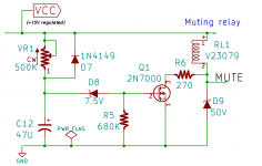
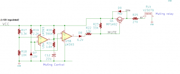
Here are two muting circuits that I've actually put into audio projects and which both worked well. At power-up they disconnect the amplifier output from its load for the first X seconds, and they also disconnect the amplifier output from its load at the very instant when the supply voltage has dropped below Y percent of its normal operating voltage.
In both cases the supply is 15V but the relay has a 12V coil, so a 270 ohm dropping resistor was added. It's a little cheaper than a 3V zener diode.
In both cases I used the Nichicon "UKL" series of low leakage electrolytics for the big RC-delay timing capacitor; as you can see, they are not expensive. I also took advantage of the high VCEmax spec (300V!) of the MPSA92, and the relatively high VDSmax spec (60V) of the 2N7000. So the flyback clamping zeners are unusually high voltage. This speeds up the relay turn-off pretty significantly, as many app notes and Douglas Self's book predict.
BTW the LM393 is a dual; two voltage comparators in a DIP-8.
Have fun analyzing them / simulating them / criticizing them.
_
Attachments
Nothing to criticise on them and its always interesting to see other approaches 🙂
The Zener I normally associate with using a bjt rather than FET and its high (ish) gate turn on volts. Its a useful technique though.
Some years back now I designed one using a triac.
Simple Universal Speaker Delay Using A Triac
The Zener I normally associate with using a bjt rather than FET and its high (ish) gate turn on volts. Its a useful technique though.
Some years back now I designed one using a triac.
Simple Universal Speaker Delay Using A Triac
Here is a FET version for 9 volt and higher supplies. Notice the value of the cap and resistor now.
1 Meg and 4.7uF would give the same time constant but if the 4.7uF is an electrolytic then its leakage current is rather more significant. Try it.
We can just use a single half wave rectifier rather than a bridge, it simplifies things.
The additional low value resistor I've added is good practice and greatly eases the stress on the small reservoir cap by limiting the peak charging currents.
The BS170 looks as though it should be OK.
Here is the circuit with your values.
Thanks for the information. I will give this schematic a try.
In the normally closed position, should the output signal be left floating, or should it be switched to ground? I read that somewhere.
preamp muting at power off and power on delay
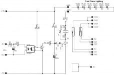
This is my design for a reed relay.
The first version was powered by AC directly from the transformer secondary output via a simple half-wave rectifier with filter capacitor. This caused hum in the signal lines that are routed in the reed relay in the contacts that are inside the coil.
This is why the circuit is now powered with DC, connected to the same clean operating voltage as the preamplifier. The relay has an operating voltage of about 2-5V. The operating voltage (30V) of the circuit is reduced for the relay by six white LEDs, which also serve to backlight a transparent front panel.
In order to make the whole foolproof, especially against fast repeated switching on and off, the secondary AC of the power supply is monitored by the optocoupler. As soon as the device resp. the AC voltage is switched off, the capacitor C2, which determines the switch-on delay time, is actively discharged via T2, R3; the delay time always starts safely from 'zero'.
Attachments
Thanks for the information. I will give this schematic a try.
In the normally closed position, should the output signal be left floating, or should it be switched to ground? I read that somewhere.
For a preamp it is preferable to arrange that the relay is normally closed and shorting the signal to ground. This avoids the relay being in the signal path for normal listening.
Most small signal circuitry is short proof, however it would be good practice to add a series low value resistor before the relay. This will allow the drive circuitry to assume normal operating conditions. For example an opamp output that was directly shorted would not allow the feedback network to stabilise the DC conditions, add a few tens of ohms and it will.
I too have a similar design here:
MOD: Mini Output Delay - a headphone / line-level audio output delay retrofit PCB
MOD: Mini Output Delay - a headphone / line-level audio output delay retrofit PCB
 a very neat PCB and implementation.
Mooly thanks so much for all the help. I'm really not that knowledgeable when it comes to designing electronics, but I do like building stuff.
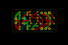
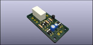
I've designed a PCB according to your schematic and sent out the order.
If anyone is interested I can share the gerber files. I haven't received and tested them yet so no guarantee I haven't made some very obvious design mistake.
I have another question about switching the outputs to ground. I have speaker protection board that I use with a single ended class D amp (IRS2092 L25D). When the module is muting the speaker outputs, it leaves the signal floating. Is it better to pull it to ground?
Attachments
Power amp outputs must never ever be shorted to ground. We always arrange for those to disconnect the speaker by the relay going open circuit. In other words the amplifier output does indeed float.
Preamp outputs are a different matter and these are nearly always short circuit proof.
Because of the very low signal levels involved in a preamp it is best to short to ground so that the signal never passes through any contacts.
Preamp outputs are a different matter and these are nearly always short circuit proof.
Because of the very low signal levels involved in a preamp it is best to short to ground so that the signal never passes through any contacts.
- Home
- Amplifiers
- Power Supplies
- Relay cut-off / mute