Absolutely fine to to that. Just push it in the board with the correct orientation and gently turn the transistor so the legs aren't shorting.
Ok, i see. I can have some KSC2383 with correct pin layout, would it work to replace the 2SC2603 as well?
https://media.distrelec.com/Web/Downloads/_t/ds/onsemi_KSC2383YTA_eng_tds.pdf
Last time the amp was power on i noticed that the Q698 was so hot it was barely touchable and the PCB under it was slightly darkened what does it do?
Should i replace this and the R698?

https://media.distrelec.com/Web/Downloads/_t/ds/onsemi_KSC2383YTA_eng_tds.pdf
Last time the amp was power on i noticed that the Q698 was so hot it was barely touchable and the PCB under it was slightly darkened what does it do?
Should i replace this and the R698?
I'll have another look tomorrow but that part of the circuit doesn't compute... collector of Q698 shown as grounded and emitter marked at ??? 34 4 volts. Can not be positive because that reverse bias an NPN transistor. Its shown as going -34 that you have circled. That is OK polarity wise.
The circuit is a text book current source/sink with current limit set by R699. When the voltage exceeds around 0.6 volt transistor Q699 turns on and limits the current at that set value. So 0.6/27 gives a current value of 22ma approx. 34 volts across the transistor would dissipate 0.022*34 which is 0.7 watt. If there is no heatsink fitted then it will run pretty hot. That would be normal.
If there is around 0.6 volts across that 27 ohm it is all working correctly.
What does it do... well the only thing it can do as it is drawn is to provide a constant current loading to the -34 volt rail.
The marked voltages are all wrong around the transistors. They must all be negative in value.
I replaced the D91, R97, Q91, Q93 and Q97 today. And yes, i crossed the emitter pin over the C and B pins to have E C B like the 2603 on the BC546. Connected the DBL with a 30w bulb but with power on the S1 relay would not activate. Then i bypassed the DBL and then the F1 1,25 A fuse blowed. Now what? Could a shorted LC7818 have blown the fuse?
Its unlikely the 7818 would blow the fuse because the +19 volt regulator if working correctly should (would) limit the current. So much has happened with this that the possibility for errors is very high I'm afraid.
I would keep the bulb in place and as a first step measure what the raw unregulated rails are. If the bulb lights up (did it light up???) then that is telling you excess current is being drawn.
Measure the voltage on Q91 emitter which is the 'raw' unregulated +34 volts and see what is present using the DBT. Do the same for negative 34 volt rail which is on the emitter of Q92.
Ok, yes the bulb did light up.
I have ordered new fuses, when they arrive i will power on with DBL and take some measurements at the Q91 and Q92 and see what i find.
I have ordered new fuses, when they arrive i will power on with DBL and take some measurements at the Q91 and Q92 and see what i find.
👍 and depending on the result you then have to start isolating sections to see if anything is pulling the voltage down and drawing to much current.
Now i have measured Q92 with DBL and have -20 volts and at Q91 i have only 15 Volts and the DBL glows some.
Before i measured i replaced the TIP42C with the orignal 2SB1015 as i found that TIP42C was NOT isolated on the back where it mounts on the heat sink which may have caused the shorting, blowing the fuse?
The case of the TIP42C also is Collector like pin 2.
Next step would be full power on?
Before i measured i replaced the TIP42C with the orignal 2SB1015 as i found that TIP42C was NOT isolated on the back where it mounts on the heat sink which may have caused the shorting, blowing the fuse?
The case of the TIP42C also is Collector like pin 2.
Next step would be full power on?
I hadn't realised the originals were an insulated package, I should have spotted that. The TIP42 will need cooling and that means an insulating kit to mount it.
I think a first step might be to isolate the LC7818 chips from the 19 volt rail and then see if that rail comes up to 19 volts. Do the chips feel warm when powered up and you have this 15 volts instead of 19 volts? Is one warm and the other not perhaps?
Each chip can be isolated by lifting these diodes.

There may be excess current draw on the 19 volt causing the bulb to glow and the rail to be low. This is the type of situation where the bulb saves things getting zapped.Now i have measured Q92 with DBL and have -20 volts and at Q91 i have only 15 Volts and the DBL glows some.
I think a first step might be to isolate the LC7818 chips from the 19 volt rail and then see if that rail comes up to 19 volts. Do the chips feel warm when powered up and you have this 15 volts instead of 19 volts? Is one warm and the other not perhaps?
Each chip can be isolated by lifting these diodes.
I replaced the R101 cbn 4,7 ohm (measured 7,5 ohm) with a mtl 4,7 ohm resistor. All other resistors measured good.
W/o the DBL i have -33 volts at Q92 and 29 volts at Q91 emitters, function diodes have 18.5 volts, BUT the RL1 have no power. No volts at R21 and R22 or D18.
Pin 6 on IC1 have 4,5 volts pin 5 0 volts.
Q11 have -33 volts at emitter and -32 volts at the base, nothing at the collector.
Q10 have 4,25 volts at the collector.
Q13 have 4,5 v at the emitter and base, -32 at the collector.
I have 19 volts at pin 22 and -19 at pin 9 on IC756 LC7818?
After all these measurements I thought I'd check the condition of the other of the two 1.25A fuses and it had blown too! Replaced this and suddenly RL1 worked and the voltages seemed to measure fine. BUT, if I play a CD and have the radio on at the same time, distorted sound comes from it, so the sound from these is mixed regardless of which function button is pressed. Is this a sign of a fried IC756 LC7818?
In other words, the sources AV1, AV2, CD, Tuner and Phono is not separated well as they should be. What may be the cause of this?
It is certainly possible the chip could be at fault.
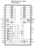
Do the LED indicators for source selection look normal. Just one on at one time? If so then we can assume the logic to the chip that decides which input is selected is OK.
The same logic levels drive all the LED's. So are all these normal (just one LED on at a time)


Do the LED indicators for source selection look normal. Just one on at one time? If so then we can assume the logic to the chip that decides which input is selected is OK.
The same logic levels drive all the LED's. So are all these normal (just one LED on at a time)
Attachments
Ok. Yes the indicators for source selection look normal, one on at one time. Everything seems to work as it should except this "crosstalk".Do the LED indicators for source selection look normal. Just one on at one time? If so then we can assume the logic to the chip that decides which input is selected is OK.
The same logic levels drive all the LED's. So are all these normal (just one LED on at a time)
The crosstalk is worse on AV1 and AV2, then on CD, Tuner and Phono. I have the cover off again and intend to check the 5 R788 and the diodes D771-773 to see if there is a problem there.
It does sounds like the chip is the most likely. Also remember the manual shows there are four of these LC7818 chips in there 🙁
I don't know what to suggest really. Ultimately you have to check them by substitution with a know good one. I wonder if you could remove all four and then replace one at a time begininning with the main input selector. Ideally a socket could be fitted and you could test all the other three then in that position.

I don't know what to suggest really. Ultimately you have to check them by substitution with a know good one. I wonder if you could remove all four and then replace one at a time begininning with the main input selector. Ideally a socket could be fitted and you could test all the other three then in that position.
I found one pin on each R788 and R782 shows 14k instead of 22k. I don´t know if it helps but i will replace these if i can find them. Is it possible to cut down a resistor network from f.e. 8 pins to 6 pins or just cut the extra leads?
The store sells only 2000 at the time of the 6 pin resistor i need but 1 each of all other, my usual luck.
Or would it be better to build an own network resistor from single resistors?
I have been searching for 30 pin sockets to no avail.
The store sells only 2000 at the time of the 6 pin resistor i need but 1 each of all other, my usual luck.
Or would it be better to build an own network resistor from single resistors?
I have been searching for 30 pin sockets to no avail.
I really can't see those being at fault. They are just 'pull up' resistors, needed because the BA612 is an 'open collector' output which simply means without a load resistor the pin is effectively floating.
To get a true reading you must unsolder one end of the resistor you suspect and re-measure. You can not test them in circuit... and they won't be faulty, honest 🙂
IC sockets you can cut down so you might be able to use two 18 or 20 pin ones.

To get a true reading you must unsolder one end of the resistor you suspect and re-measure. You can not test them in circuit... and they won't be faulty, honest 🙂
IC sockets you can cut down so you might be able to use two 18 or 20 pin ones.
Ok, i´ll let the R782 and R788 be for now.
I have ordered 2 new LC7818 and 2 32 pin sockets which i´ll cut down to 30 pins.
It will be a challange to remove the old LC7818, any tips? Hot air gun or cut the pins?
I have ordered 2 new LC7818 and 2 32 pin sockets which i´ll cut down to 30 pins.
It will be a challange to remove the old LC7818, any tips? Hot air gun or cut the pins?
Use solder braid. It should come out in two minutes and look as good as new. You need a hot iron with a decent fairly large tip. Practice on something scrap first. It is an acquired skill like most things but you should be able to desolder each pin in around 2 seconds per pin once you get the knack.
A 32 pin socket might physically fit with no cutting apart from chopping a couple of legs off.
A 32 pin socket might physically fit with no cutting apart from chopping a couple of legs off.
Look at these:
I would use a bigger tip than this guy.
Braid comes in different widths. I would get wider rather than narrower.
This is the iron I use. You can see the tip size.
https://www.diyaudio.com/community/...ow-to-do-it-without-specialised-tools.127924/
Braid comes in different widths. I would get wider rather than narrower.
This is the iron I use. You can see the tip size.
https://www.diyaudio.com/community/...ow-to-do-it-without-specialised-tools.127924/

- Home
- Source & Line
- Analog Line Level
- Relay control?