Hello, i have a +/-90v psu that i built.
I also have a irs2092s amp that takes the +/-90v.
Would i be able to put two relays between the psu output and the irs2092s input, one relay for each side of the +/- voltage.
I worry that suddenly relaying +/-90v to the irs2092s amp would blow it up.
Perhaps i could use inrush resistors behind the relays? I have a few NTC-5D.
Though, could the inrush resistance cause unequal voltage buildup?
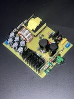
Here is the schematic of my diy smps:

Amp module:

I also have a irs2092s amp that takes the +/-90v.
Would i be able to put two relays between the psu output and the irs2092s input, one relay for each side of the +/- voltage.
I worry that suddenly relaying +/-90v to the irs2092s amp would blow it up.
Perhaps i could use inrush resistors behind the relays? I have a few NTC-5D.
Though, could the inrush resistance cause unequal voltage buildup?
Here is the schematic of my diy smps:
Amp module:
The TL494 has a soft start function; the PWM rise time is set by the capacitor value, i.e. the voltage at the PSU output will increase smoothly, not quickly.I worry that suddenly relaying +/-90v to the irs2092s amp would blow it up.
Try to avoid using relays contacts to switch DC as they will not live as long as one would like certainly when the load is capacitive. Also avoid using 2 relays for + and - with possible time difference in switching moment as that would be error by design. Again avoid non linear parts to limit inrush current in the rails, these are better suited in AC inrush limiting. Anyway, just remember to not switch DC as a design habit except when it is about safety/error detection when things go south and DC needs to be shut off. Then everything is allowed to protect people and the equipment.
Besides that the design of both PSU and amplifier should allow for normal power on/off. Things really are better the normal/usual way. To avoid power on/off plops use a delayed power on, immediate power off loudspeaker relay circuit (possibly combined with DC detection).
BTW why an amplifier with +/- 90V rails? PA use? If you are the user yourself please consider to have lower rail voltages and be aware that normal listening levels usually require only a few Watts. Building high power stuff brings self inflicted but possibly undesired extra features/challenges/risks you may not be too fond of. Your ears will thank you too.
Last edited:

Maybe you can take a look at how we control supply inrush from batteries to a Class A amplifier :
www.diyaudio.com/community/threads/hiraga-le-monstre-2024.413301/post-7712921
Patrick
www.diyaudio.com/community/threads/hiraga-le-monstre-2024.413301/post-7712921
Patrick
The IRS2092 is capable of +/- 100V. However the complete amplifier needs a MOSFET power stage. As it happened I looked into this amplifier last week, but I could not find the specification for the power semiconductors. If you cannot find it, keep to the recommended supply voltage. IIRC that is +/- 65V.
If you can find it, it is easy to see (*) whether 90V is allowed.
This amplifier board is somewhat exceptional in that it is a single-ended amplifier. You don't see that so often in high power class-D designs. But it explains the high supply voltage.
Why do you want to switch DC anyway? Why not switching the AC power? As others stated, switching DC with ordinary relays is apt to premature failure. Most notably the contacts weld together and you have a single supply voltage for a long time instead of for an instant. I think that is bad.
If you you have to switch the 90VDC lines (but I don't see an explanation for that in your post) I would prefer solid state devices like IGBTs or power MOSFETs.
(*) I wanted to write this word:

But the editor replaces that with *******
Isn' t that überwokeness? Besides, the plurar of the human back part is written with a single S
If you can find it, it is easy to see (*) whether 90V is allowed.
This amplifier board is somewhat exceptional in that it is a single-ended amplifier. You don't see that so often in high power class-D designs. But it explains the high supply voltage.
Why do you want to switch DC anyway? Why not switching the AC power? As others stated, switching DC with ordinary relays is apt to premature failure. Most notably the contacts weld together and you have a single supply voltage for a long time instead of for an instant. I think that is bad.
If you you have to switch the 90VDC lines (but I don't see an explanation for that in your post) I would prefer solid state devices like IGBTs or power MOSFETs.
(*) I wanted to write this word:
But the editor replaces that with *******
Isn' t that überwokeness? Besides, the plurar of the human back part is written with a single S
🙂 I just love the word "überwokeness". Woke is a terrible contagious disease disrupting harmony in society.
The pictured module only has 80V electrolytics and should be used with +-65 Volt. The PCB is 100x50mm and the heat sink will not be able to keep the semi conductors alive, even with the tiny fan. In most cases these boards have fake MOS Fet's unable to deliver the needed current, if you are lucky you get some recycled from scrap that will be in spec.Why exactly? The IRS2092 is capable it seems (from paper).
Why would anyone feed a +/- 65V device with possible fake semis and 80V electrolytic caps on +/- 90V? So it is true that the western population is dumbing down?
He is from England. That's not Europe any more...
but serious: You may trust something a seller writes about a product. Not anyone has had prior experience with the Asian way of selling things.
We think that a merchant should have at least basic knowledge of what he sells. That is not true in 99% of Aliexpress sales. The don't know and don't care what they sell, so asking for help is 100% useless. Often they hope to have an advantage compared to others selling the same stuff by exagerating data they think are important. Like Watt, Voltage etc. Ohm for example is broadly unknown. Don't complain about our education system until you send your children to school in China. The great thoughts of emperor Xi Jinping are more important than western science.
If you buy Aliexpress products, be sure you can figure out how to use it, solve problems and be able to take the loss with no refund, if things go competely wrong.
High, thanks for all the responses. No offence meant but please keep it to the topic, I'm not trying to talk about the western population right now.
I made a mistake with my post, the smps i designed and built puts out +/-80v not +/-90v 😭.
The pictures model has 100v caps.
The irs2092s module i am using CAN handle this, and at the moment it puts out 400w into 4 ohm, after about 10 mins of this it the amp was too hot.
It is being used on subwoofers.
I will take the advice not to put relays between my already turned on psu and the irs2092s module.
The reason i need to turn on the power between the psu and the amp is that the psu has a 5v output that powers a bluetooth module, connected to the amp.
If everything power up at once, the bluetooth module outputs some horrible noise as it turns on.
I have to have the bluetooth module already powered on, before the amp.
I might give the bluetooth module its own dedicated supply, then put a relay on the 240vac input to my psu that is switched on after the bluetooth module has already been on a couple of seconds.
Attachments
In that line of thinking a Meanwell IRM module is what is needed. Better have that Bluetooth module transmitting happiness in the air 24/7 than having an unattended high(er) power SMPS staying energized.
Or the arguably best method: add a tiny muting PCB shorting the BT modules outputs to GND at power on for the required time. That would be my way of working. Just like in japanese built gear from the eighties. I made such a PCB but I am waiting for the parts. Gerbers will be available after testing.
Or the arguably best method: add a tiny muting PCB shorting the BT modules outputs to GND at power on for the required time. That would be my way of working. Just like in japanese built gear from the eighties. I made such a PCB but I am waiting for the parts. Gerbers will be available after testing.
Last edited:
The second part is true. After testing the 500w irs2092s modules from aliexpress i have found that the ones that actually use legitimate irs2092 chips and legitimate mosfets are the “v2” versions.He is from England. That's not Europe any more...
but serious: You may trust something a seller writes about a product. Not anyone has had prior experience with the Asian way of selling things.
We think that a merchant should have at least basic knowledge of what he sells. That is not true in 99% of Aliexpress sales. The don't know and don't care what they sell, so asking for help is 100% useless. Often they hope to have an advantage compared to others selling the same stuff by exagerating data they think are important. Like Watt, Voltage etc. Ohm for example is broadly unknown. Don't complain about our education system until you send your children to school in China. The great thoughts of emperor Xi Jinping are more important than western science.
If you buy Aliexpress products, be sure you can figure out how to use it, solve problems and be able to take the loss with no refund, if things go competely wrong.
Since I worked in China I have seen the broad possibilities and clever engineers but also the general way of working. It is different.
It uses 100v caps.Why would anyone feed a +/- 65V device with possible fake semis and 80V electrolytic caps on +/- 90V? So it is true that the western population is dumbing down?
It is not limited to +/-65v. The highest i would personally go is +/-80v, and this video demonstrates it running at +/-90v:
I even got a pair of LJM IRS2092s amps, but changed the the large parts before using it. Too many had reported them blowing up after a few minutes without any recognizeable cause. In general you can use those parts from Ali, but you have to be carefull and check for traps. It helps to read the bad experience others had.
With the IRS2092s the main problem is that it can not drive the larger MOSfet's needed for more than +-55 Volt. It would need an extra driver stage in between, but you will not find it on most (all?) of these boards, they simply replaced it with good hope. A nice idea is to fit a small heatsink on the IRS IC. Another problem is the additional voltage the IC needs, they generate it on the board, which produces heat (with the linear regulator) or problems (with the switch mode chip).
Last, these boards are not reliable with 4 Ohms, usually only 8 Ohms allowed.
Sound in general is OK with a sub.
- Home
- Design & Build
- Electronic Design
- Relay between smps and amp?