Member
Joined 2002
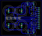
Ok it took me a week to learn eagle with some help from Jens Rasmussen i did a layout then he changed it to single sided. I will pot the board layout to see what people think and i welcome any suggestions and comment's. It is based of Nelson Pass's Regulator for the Zen amplifiers i saw it and wanted it for my personal use for some amps i have here at home. if any one is interested in a few boards please post it so i can see if we should start a group Buy.
Attachments
jleaman said:Ok it took me a week to learn eagle with some help from Jens Rasmussen i did a layout then he changed it to single sided. I will pot the board layout to see what people think and i welcome any suggestions and comment's. It is based of Nelson Pass's Regulator for the Zen amplifiers i saw it and wanted it for my personal use for some amps i have here at home. if any one is interested in a few boards please post it so i can see if we should start a group Buy.
Where are the input and output connections?
--
Brian
Member
Joined 2002

Member
Joined 2002
Jason
I think you can make a better layout if you use two layers.
Also I think that fuses might be a nice feature along with some connectors or solderpads.
\Jens
I think you can make a better layout if you use two layers.
Also I think that fuses might be a nice feature along with some connectors or solderpads.
\Jens
Member
Joined 2002
Ok I ll try a new layout tonight then when i get home ill be up if you want to chat again Jen's. Im also thinking maybe some fuses and a led showing it is on and the bridge rectifier on board so all that is needed is the tranny Directly connected to this board.
1) Fuse per rail.
2) led Status Light
3) input / out put Terminal's
4) Onboard Bridge Rectifier's using a bridge or Fred's.
1) Fuse per rail.
2) led Status Light
3) input / out put Terminal's
4) Onboard Bridge Rectifier's using a bridge or Fred's.
Member
Joined 2002
Ok i have improved the board and now i shal get one etched to see if it work's. I have some questions on what diodes to replace / change to lower the output rail voltage. Maybe some tips from nelson or some one ?
Member
Joined 2002
Of course and ill share it too : O ) I'm adding a few things tonight.
Ie power terminals
Output terminals
Led Power.
Dual secondary's Instead of one.
Thicker traces.
Maybe more cap's possibly 6 instead of 4.
I'm planning to use these for 2 thing's. One maybe if possible for my mini a's to bring down the voltage to 20v rail's and for my other blue amps that run on 40v rail's..
Hope it work's.
For 20V rails, just use two 10V zeners per side, and link the unused pads. For 40V, use two 20V zeners per side.
Member
Joined 2002
Maybe your confused. 'Im building regulated psus for a 40v amp and another for the mini a's. : O ) so all i'll have to do then is change the parts that are needed ?
I'm not confused, are you? 🙂
Yes, you just need to change the zeners to get the voltage you want. You may need to check that the 240s are stiil in their SOA if you plan to pull a particularly high current from them.
Yes, you just need to change the zeners to get the voltage you want. You may need to check that the 240s are stiil in their SOA if you plan to pull a particularly high current from them.
Member
Joined 2002
my Blue amps only pull a few amps and i hardly crank them. There not for subwoofers or any thing witha hi load. Just a simple amp that id like to see if regulated makes any difrence at all. What does SOA mean ?
Member
Joined 2002
pinkmouse said:Safe Operating Area. It is shown as a graph of current against voltage on the datasheets.
AHH i see thanks..
Got any ideas for what other devices i can use just to be safe ?
Sorry Jason, I'm not hugely familiar with mosfet types. Still, I'm sure someone here can advise.
Can't you design the regulator to piggy back onto BrianGT's power supply boards to avoid yet more capacitors. Maybe you could make it so you can connect it between the first and second bank of caps where the inductors ar bridged or load resistors.
Regards
Anthony
Regards
Anthony
Member
Joined 2002
For 20V rails, just use two 10V zeners per side, and link the unused pads. For 40V, use two 20V zeners per side.
The Fets dispose at least 4 volts, so you need to add that to the zener string.
4) Onboard Bridge Rectifier's using a bridge or Fred's.
A regulator like this is meant to sit after a raw supply, so you dont want the diodes here.
Maybe you could make it so you can connect it between the first and second bank of caps where the inductors ar bridged or load resistors.
I dont think it is a good idea with big caps after the reg. It might oscilate.
You might want to check if it is possible to make a output sensing
connection (to the amps output) to modulate the supply's voltage. This will increase the amps overall efficiency.
Steen 🙂
Edit. You dont need 1000uF caps for this application. 220uF is enough. the circuit works as a capacitance multiplier.
- Status
- Not open for further replies.
- Home
- Source & Line
- Analog Line Level
- Regulator Board ( group Buy )