Hello everyone!
Thanks to all of the useful information from you guys, I was able to narrow down the problem on my 6N2/EL34 kit amp build to the output transformers. I had installed both of them backwards due to the lack of markings and the fact that the winding connections to the poles were covered. I should have probably tested them with my multimeter retrospectively, but an oscilloscope and sample tone helped me figure out and rectify the issue.
My amp now makes sound, however there is a constant hum present on one of the channels, even when there is no audio input connected. I swapped both of my output tubes and the hum was present on the other channel, so my tube might just be bad. I’ve ordered a matched set, but I am quite concerned about my heater voltages. The 6.3V tap from my power transformer reads 7.3 volts and I’m sure that’s the cause of all of the tube/hum issues.
Would it be a better idea to put a 1 ohm 10w resistor between the transformer and the filaments, or build a 5A DC regulated power supply (probably based on the LM317)? Also, my amplifier has the filaments directly connected to the 6.3V input. Would it be wise to add in a small value capacitor and a couple of 2W 300-600 ohm resistors between the filaments and ground?
Any help is much appreciated! Thanks!
Attachments

If it is mains hum, I would remove the ground side of the heater tap and insert a virtual earth; two 100R resistors in series across the 6.3v winding and the centre of the resistors to be connected to ground.
Calculate the freq using your scope,measuring the OP with no sig IP , that is if your scope doesn't have a readout. Count how many square's from peaks, x by time/div setting, then divide into one, EG 4 divs between peaks, timebase set to 5mS/div, 4x5=20mS, so 1/0.020 = 50 (hz), apologies if you know this.This is a good circuit if you can't solve your hum issues by a humdinger or sorting the ground connections, see attached.
Andy.
Andy.
Attachments
If the noise moves on other channel there is a problem in one EL34 due, p.e., to a low leakege from cathode to filament.This is one of the parameter that is not frequently tested by tube supplier
When this happen you get a hum.
Wait for a new EL34 and test.
About filament voltage start with 1 ohm if it too much ut in parallel a value to get the 6,3 volt under load.
Walter
When this happen you get a hum.
Wait for a new EL34 and test.
About filament voltage start with 1 ohm if it too much ut in parallel a value to get the 6,3 volt under load.
Walter
For EL34 output stages, ac-heating should be OK. Ground the centre-tap of the heater-winding, if it has one, otherwise, make a centre-tap as suggested above.
running at 7.3V will not usually increase the hum, but adding resistance to fix the heater overvoltage is worth the trouble, because the cathode coating will degrade fairly quickly with +16% of Uh.
running at 7.3V will not usually increase the hum, but adding resistance to fix the heater overvoltage is worth the trouble, because the cathode coating will degrade fairly quickly with +16% of Uh.
Thank you for all the responses! I will order some high wattage 1 ohm resistors today and go ahead and build a virtual ground. I should be able to analyze the hum using the oscilloscope,
My tubes were also getting quite hot. The thermocouple on my Fluke DMM registered 325°F on the surface of my EL34’s. I did not have an IR one on hand to test the mica within the envelope. I’ve read that up to 450°F is normal for power tubes being driven hard, but is this normal? I’m assuming mine would have been slightly higher than normal due to the filament voltage and I’ll retest it once I get those 1-ohm resistors in line but I had wisps of smoke coming off the top of the tubes (first real run)
Currently I’ve got 100 ohm 2W resistors in my parts kit. That should be sufficient for creating the virtual ground.
> 325°F on the surface of my EL34’s
That's OK. Glass envelope temperature of 200°C (392 °F) is a typical limit for power valves.
Beyond that, checking the anode dissipation is all that's needed:
((Va-Vk) * Ia) <25W (Limit) 20W typically, for EL34.
That's OK. Glass envelope temperature of 200°C (392 °F) is a typical limit for power valves.
Beyond that, checking the anode dissipation is all that's needed:
((Va-Vk) * Ia) <25W (Limit) 20W typically, for EL34.
Before you make a virtual ground check if with new EL34 you got same same noise.
If not leave the original configuration just with an adjustment on voltage
Walter
If not leave the original configuration just with an adjustment on voltage
Walter
I brought home my IR therm from work, so I’ll be able to get a decent reading now. Ordered 1-ohm 10W resistors and my matched tube set is being shipped so I’ve got to wait a few days. Since I’ve got screw terminals for the power supply inputs on the PCB, I might solder a little pcb with the virtual ground setup so it can be removable (if the tube really is the problem).
I’ll take a look at my anode dissipation. I think my B1 voltage is hovering around ~260VDC once the tubes warm up. Would it be wise to add in a standby switch between the hv supply circuit and the power transformer input? Furthermore, If I add an adjustment to the B1, B3 voltages, would that serve as an adjustable bias?
Again, thanks to all for all the help!
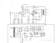
So I decided to run the amp again just to verify that the high temps I could feel were from the power tubes and nothing else. Turns out that two of my resistors in the power circuit, R1 and R2 were beginning to overheat and discolor. If you look at the schematic (I attached it again) these are the first two resistors after the diode rectifier, so with 262VAC in (works out to ~370VDC after rectification if I remember correctly). Should I just replace these for higher wattage resistors, or is there something else causing a significant power draw?
Put a couple of 6W 300-ohm resistors in place of the 3W ones but they were still getting abnormally hot (180°+). Is this normal for the power supply? I would hate to put a new pair of tubes in and have them get damaged.
I’m going to get my hands on another DMM and get the current flowing across R1/R2. I was hesitant as my current meter is fused up to 440mA but I can grab one from the shop that should be fused at 10A.
I’m going to get my hands on another DMM and get the current flowing across R1/R2. I was hesitant as my current meter is fused up to 440mA but I can grab one from the shop that should be fused at 10A.
Last edited:
You just need to measure the voltage drop across the resistors to calculate the current (I=V/R), and once you have that you can calculate power being dissipated (P=VI). Rating of the resistor should be at least twice the power dissipation.
> Put a couple of 6W 300-ohm resistors in place of the 3W ones but they were still getting abnormally hot (180°+).
High Power Wirewound resistors are often rated to operate at 300°C [572 °F], so that is likely to be normal. But you may prefer the operating temperature to be lower - easily achieved by parallel-multiple parts, or higher ratings.
You can use the data sheets as a guide. This one is for the Welwyn W2x series - good quality vitreous-enamelled wirewounds, very good for audio builds.
The curves at the bottom-left of page 1 show how hot you'll get for the power dissipation, for each power-rating.
https://www.ttelectronics.com/TTElectronics/media/ProductFiles/Resistors/Datasheets/W20.pdf
You just need to measure the voltage drop across the resistors to calculate the current (I=V/R), and once you have that you can calculate power being dissipated (P=VI). Rating of the resistor should be at least twice the power dissipation.
What OldHector said.
Measure the voltage drop across the 2 resistors...lets say 25 volts. The 2 resistors together have a resistance of 150 Ohm.
Therefore 25/150=0.166666 Ampere. Multiply by a thousand to get mA.
0,16666 * 1000 =166mA
That first of all would be too much current for a SE with 6N2 and EL34.
So that gives us a lot of info.
Secondly calculate the power the resistor has to handle. (P=VI)
VI = Voltage * Current. Voltage measured in volts. and Current in A.
So 25*0.166666=4.16 W.
You generally want to over engineer. So get something 3 times the wattage IF that really was the case.
So I got the other DMM and connected it to the HV in line on the PCB. The two EL34's and the 6N2 were pulling a combined 220mA. When I removed the bad tube, the current dropped to 80mA for one EL34 and the 6N2. Probably explains why my resistors were burning up. I also measured exactly 400VDC right past the rectifier diodes. With two resistors wired in parallel for each section and if my math is correct,
B1 would have a voltage drop of (0.08)(150) = 12V drop across the first set of resistors with power dissipation of (12)(0.08) = 0.96W dissipation.
Drawing 220mA, the Vd would have been (0.22)(150) = 33V dissipating 7.26W. Makes sense.
I also connected a speaker to the side of the amp that had the working EL34 and it was very clean.
Do those numbers look decent for a single EL34 and a 6N2? Sounds really good and looks clean on the scope but the resistors were still getting a bit hot and I didn’t run it for more than a few minutes for testing.
- Home
- Amplifiers
- Tubes / Valves
- Regulating Filament Voltages