I am going to build Broskie's Aikido preamp, but would like to regulate the power supply. I only need around 15ma, but would like it to be hum free - and with no pops when the air conditioner cuts on/off. What do you think about this idea (see schematic)? Regards, Bill.
Attachments
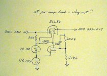
Rather complicated circuit when a simple VR150 & VR75 tube in series will net the same +225 with only 1% or so less regulation. The VR tubes should have a .1uf capacitor placed across the output to remove some noise plus a small choke on the output for best noise reduction.
Fact is, an unregulated LCLC is reported to provide superior sonics. I am not sure why.
Fact is, an unregulated LCLC is reported to provide superior sonics. I am not sure why.
amperex said:Fact is, an unregulated LCLC is reported to provide superior sonics. I am not sure why.
I thought I read somewhere the output Z of a single VR tube was in the range of 200 ohms. Is that correct? If so the last C in a LCLC would easily be much lower (though my guess is the effect on performance would still be circuit dependent.)
Bill*B said:I only need around 15ma, but would like it to be hum free - and with no pops when the air conditioner cuts on/off.
Hi Bill,
Which tubes will you be using for the Aikido? Will one regulator drive both channels? The reason I ask is I'ld like to build one myself and am looking for tubes that are in a nice linear region biased at lowish currents (3.75 ma in your example for a single reg) and don't mind cathode to heater voltages over 100 volts.
kmtang said:The use of the VR tubes could be rather noisy. Filtering is needed at the output.
You could simply use L-C-L-C filtering for very good result.
Johnny
I use VR tubes to regulate my phono stage with no noise issues...along with CLCLC filtering before hand.
Thanks for the input, all! I'm planning on using 12ah7 tubes for the signal section. With 1K cathode resistors they should pull about 10ma per side at 225V, or around 15ma with 300V (which would pretty much max them out). I'd considered a CLCLC passive PSU, but hoped the active regulator would produce less ripple. Bill.
Hi,
Only, you'll have a shunt regulator. One that doesn't like to see a capacitive load too.
Pretty meaningless if you ask me.
Bill,
Why waste a perfectly good sounding ECL86 when you can lose a rather useless ECL85 instead?
I can't understand the reasoning behind using a series pass device with high internal resitance such as the penthode used here.
Moreover you regulate the grid as well where another VR tube is used...
Why not triode connect the penthode, use the triode as an error amp and stick a VR on the cathode end?
Cheers,")
Rather complicated circuit when a simple VR150 & VR75 tube in series will net the same +225 with only 1% or so less regulation.
Only, you'll have a shunt regulator. One that doesn't like to see a capacitive load too.
I thought I read somewhere the output Z of a single VR tube was in the range of 200 ohms. Is that correct?
Pretty meaningless if you ask me.
Bill,
Why waste a perfectly good sounding ECL86 when you can lose a rather useless ECL85 instead?
I can't understand the reasoning behind using a series pass device with high internal resitance such as the penthode used here.
Moreover you regulate the grid as well where another VR tube is used...
Why not triode connect the penthode, use the triode as an error amp and stick a VR on the cathode end?
Cheers,
Attachments
Bill*B said:Thanks for the input, all! I'm planning on using 12ah7 tubes for the signal section. With 1K cathode resistors they should pull about 10ma per side at 225V, or around 15ma with 300V (which would pretty much max them out).
Won't that make the total current draw closer to 40-60 ma for stereo ?
won't that make the current draw closer to 40 - 60 ma for stereo?
You're right - close to 30ma for signal alone - plus that required for the regulator drop. The little circuit could probably support only one side.
you'll get better performance from a Maida regulator
SY, while I'm more comfortable with tubes, I'm not entirely anti-sand - just rather ignorant of solid state design. I had to run a Google search to find what you were talking about - very interesting! Others reading this, look for National Semiconductor Linear Brief 47. What a great forum - I wanted ideas, and I'm getting plenty of them! Thanks.
why waste a perfectly good sounding ECL86
Good point. I just had a few on hand, but better tubes are too cheap to use that for an excuse.
Frank, since you were kind enough to comment (and post a schematic), may I be so bold as to ask you a question: I've been fascinated by your "ultimate preamp", and am studying the PSU design which you posted along with it (with the cascode error amplifier.) If I'm reading the circuit right, the 12AX7 runs at very low currents - maybe 1/20 a milliamp for the top half, prehaps half a ma for the lower. Is that correct, or am I missing something? I gather that you rather like that design.
All: I'm so delighted to have your help. Many, many thanks. I've gotten what I needed - good advice before starting to punch the chassis - and have concluded that my original scheme is just a bit nutty (I was thinking of regulating the screen in hopes of a bit less ripple). I guess I'll stick with a proven design.
Sy, I'm going to chew on that silicon, too. I guess if I used sand rectifiers and an LM317, I could run the output through a TV damper diode to make the DC "right" before I allowed it to touch my precious NOS 12AH7s.
All the best, Bill.Hi,
If you mean the 12AX7A as used in the error amp, yes that's correct.
It's just monitoring the 7025 and with the big capacitance behind it B+ is rock solid.
I do like it a lot indeed, for this application I think it's hard to better. Closest to the an active battery supply I can think of.
Cheers,
If I'm reading the circuit right, the 12AX7 runs at very low currents - maybe 1/20 a milliamp for the top half, prehaps half a ma for the lower. Is that correct, or am I missing something? I gather that you rather like that design.
If you mean the 12AX7A as used in the error amp, yes that's correct.
It's just monitoring the 7025 and with the big capacitance behind it B+ is rock solid.
I do like it a lot indeed, for this application I think it's hard to better. Closest to the an active battery supply I can think of.
Cheers,
SY said:You'll get much better performance from a Maida regulator. Simpler and very reliable.
(ducking for cover)
holy flying brickbats, a floating LM317 ?
this is my disemboweled Fairchild 255 with a floating LM317 Regulator:
An externally hosted image should be here but it was not working when we last tested it.
it works very nicely, and takes up lot less space than trying to fit some VR tubes onto the chasis!
Nice iron in those Fairchilds. I've got a pair of them myself.
Bill, why throw away the excellent source Z performance of the Maida by adding a big old high impedance component after it? Simplicity! Two excellent tube implementations of the Maida regulator were published by Joe Curcio in Glass Audio (his ST-70 rebuild article) and Morgan Jones in "Valve Amplifiers." I use the Curcio implementation in my preamp and in two of my power amps. Over 10 years of use with no failures.
Bill, why throw away the excellent source Z performance of the Maida by adding a big old high impedance component after it? Simplicity! Two excellent tube implementations of the Maida regulator were published by Joe Curcio in Glass Audio (his ST-70 rebuild article) and Morgan Jones in "Valve Amplifiers." I use the Curcio implementation in my preamp and in two of my power amps. Over 10 years of use with no failures.
Hi,
Seven pin VR tubes hardly take up more space than a LM3xx.
Look who's talking about stuff taking up space anyway....
Cheers,
it works very nicely, and takes up lot less space than trying to fit some VR tubes onto the chasis!
Seven pin VR tubes hardly take up more space than a LM3xx.
Look who's talking about stuff taking up space anyway....
Cheers,
Sorry I'm late in this thread...
The first posted schematic won't work very well. If at all. To get 225V output, the screen on the pass tube is at a mere 30V. You can remove the top VR tube altogether. A small cap across the VR tube, which can be a lower current unit such as 0G3, will cover regulation and noise good. Or a zener string with generous electrolytic bypass.
If you want even more regulation, you can add a VR from output to error amp grid. That way the error amp's grid and cathode are locked between two voltage sources, improving regulation a few dB. Beyond that, a pentode error amp or several cascaded stages (preferably balanced for stability) will be required for better performance. But none of this is necessary, of course.
Even for a class A phono stage, careful grounding and a conservative CLC filter will do more than any regulator will.
Tim
SY - I was just kidding about the damper tube, but until I get more comfortable with solid state, will probably stick with a tube circuit. I do agree that solid state can do just as well (or better) in competent hands.
Sch3mat1c - thanks for taking the time to help. I agree, in my mind I've abandoned the original circuit.
One more decision that the thread has prompted - I'll plan to use a two chassis design, so that I can swap power supplies if I get the urge to experiment. Regards, Bill.
Sch3mat1c - thanks for taking the time to help. I agree, in my mind I've abandoned the original circuit.
One more decision that the thread has prompted - I'll plan to use a two chassis design, so that I can swap power supplies if I get the urge to experiment. Regards, Bill.
Hi,
With the LCLC PS you already have it would hardly be useful to add a regulator, especially so within the context of the Aikido circuit which sports superior PSR as it stands.
Cheers,
If I were to add a regulated supply, I would be looking at a shunt regulator rather than a series regulator.
With the LCLC PS you already have it would hardly be useful to add a regulator, especially so within the context of the Aikido circuit which sports superior PSR as it stands.
Cheers,
dmcgown - Great! I'm encouraged to hear that. The main reason I've settled on the Aikido is because my last project (a simple little volume pot/cathode follower) has audible hum with my 87 db mini-monitors, doubtless due to the fact that I paid insufficent attention to mechanical layout. By the way, is your concept of the output stage on the Aikido that it is just a cathode follower with a (sort of) constant current source load? The 12BH7 linestage which Frank posted under the Aikido thread is a White cathode follower, if I'm reading it right. The Aikido isn't a true White, is it?
Frank - I've been sweating, trying to understand the error amp shown in your "Ultimate" post. You seem to have tweaked the basic cascode with a couple of unique twists.
1) That 220K resistor from 305V reg to plate lets the lower triode run with more current than it could with just that provided by the upper triode, but I don't understand WHY that's important.
2)The voltage divider to BOTH grids (rather than just grounding the upper grid): I assume that this sets the operating parameters for the two triodes, giving 100V across the lower triode, and allowing about 120V of space for the upper triode/plate resistor - which along with the very high value upper plate resistor, forces the upper triode to operate with just a "trickle" of current, providing more gain. Does this ALSO "bootstrap" the upper triode, by providing positive feedback, and further boost the gain? If so it must have a fantastic overall figure.
My last question: is the huge capacitor bank essential to this reg? Would you expect it to be happy with, say, 50 uf before and after, instead of 300 plus? Wow! - I hope that long winded rush hasn't made your head spin. By the way, THANK YOU (and all) for your patience with me.
Best regards, Bill.
- Status
- This old topic is closed. If you want to reopen this topic, contact a moderator using the "Report Post" button.
- Home
- Amplifiers
- Tubes / Valves
- Regulated PSU, your comments please.