grege said:
Electus Distribution Pty. Ltd. (formerly John Carr & Co. Pty. Ltd.)
John Carr -> J. Carr -> Jaycar What do you think? Electus is probably Jaycar's distribution company? And the product codes look very familiar.")
Part numbers for Electus and Jaycar are identical! And brands also; e.g. Samxon caps.
D_GR8_1 said:Will a 28-0-28/300VA transformer be enough to drive 2xLM4780 chips?
no, i would go for something bigger considering that one chip practically is two lm3886 and so can put out 270W peak.
I myself use one 160W trannie per channel.
a friend of mine who bought the lm4780 kit from brian gt went for a 800w 24-0-24 xformer. he got it very cheap though.
Now, how much difference in sound that is, will there be if I have separate toroid for each channel rather than 1 big one for the whole lot.
I am thinking of using a 500VA for 2xLM4780 which will be used for biamping my speakers. Next I probably will use 1x300VA for L/R Surround & Center Speaker powered by 3xLM3886.
Is that sufficiend enough or should I use 5 toroids for the 5 channels?
I am thinking of using a 500VA for 2xLM4780 which will be used for biamping my speakers. Next I probably will use 1x300VA for L/R Surround & Center Speaker powered by 3xLM3886.
Is that sufficiend enough or should I use 5 toroids
for the 5 channels?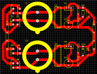
IMHO you should re-design those thin tracks you are using and put the thickest you can fit in instead.
Particularly those to and from the big caps, plus the ground tracks after the regulator up to the star point and the output V+ and V-.
I think you should draw large fill square areas, or any shape you may want, to cover the whole pcb.
Carlos
Particularly those to and from the big caps, plus the ground tracks after the regulator up to the star point and the output V+ and V-.
I think you should draw large fill square areas, or any shape you may want, to cover the whole pcb.
Carlos
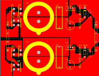
D_GR8_1 said:Hey Carlos,
is this what you mean?
It certainly is. Just watch some distances, like those close to C5, which seem a bit too close.
The rest is very much like what I would do, except that I prefer square blocks all over and leave absolute no space free, except to separate the blocks with the minimum distance between them.
Carlos
Just watch some distances, like those close to C5, which seem a bit too close.
What do you suggest should be the minimum distance between these blocks??
D_GR8_1 said:
What do you suggest should be the minimum distance between these blocks??
One millimeter is probably fine.
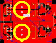
D_GR8_1 said:I got most of the distances to a minimum of 1mm, however the Regulator pins are 0.5mm apart. Is this ok?
It should be fine, or they wouldn't use it, right?
In fact, on the low current designs I use IC pin distance as the reference to separate the blocks.
Be aware that many people on this forum are against wide tracks for capacitance reasons.
Be aware that many people on this forum are against wide tracks for capacitance reasons.
I understand that, when dealing with audio signals, however this is a PSU PSB, so we need wide tracks in order to carry that High Current!!
D_GR8_1 said:
I understand that, when dealing with audio signals, however this is a PSU PSB, so we need wide tracks in order to carry that High Current!!
From the comments I got from a professional pcb designer, audio circuits are pretty forgiving and shouldn't care for large fills.
As I see it, I think large copper areas allow more flexibility during parts assembly.
I did saw arrangements too in top line Yamaha and Rotel power amps.
Carlos
- Status
- This old topic is closed. If you want to reopen this topic, contact a moderator using the "Report Post" button.
- Home
- Amplifiers
- Chip Amps
- Regulated PSU PCB