I'm about to build a powersupply for a Borbely Jfet buffer (for my buffered preamp, http://www.diyaudio.com/forums/showthread.php?s=&threadid=17132).
I was thinking of using LM317/337, but that's no fun.
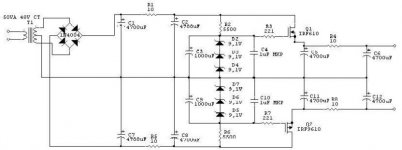
So I drew this up. But will this work good? I'm sure that there are other solutions that is much better, but I want something simple.
But it has to be reasonably free from noise.
What do you think?
/Freddie
I was thinking of using LM317/337, but that's no fun.
So I drew this up. But will this work good? I'm sure that there are other solutions that is much better, but I want something simple.
But it has to be reasonably free from noise.
What do you think?
/Freddie
Attachments
Freddie,
It will work surely, but I would re-think the 10 Ohms at the output. This isolates the regulator from the last cap for practical purposes. For hum etc, the regulator will be visible, but for load-generated ripple and as a low-impedance supply, in effect the supply consists of just one 4700uF cap. Why do yuo think you need that 10 Ohms?
Jan Didden
janneman,
I placed it there to get some filtering.
Perhaps I should remove the 10 ohm resistor?
/Freddie
Why do yuo think you need that 10 Ohms?
I placed it there to get some filtering.
Perhaps I should remove the 10 ohm resistor?
/Freddie
I use same type of regulator for my valve preamplifier. Output is 240V, the series-pass device is IRF840.
As I see the schematic, the 4700uF is too high at the source of the mosfet. It can results some oscillation, or can damage the mosfet. The 10ohms+4700uF filter looks much better. I think You can simply remove the first 4700uF caps.
To reduce the noise, apply some 100komhs+10uF between the zener strings, and the gates of the mosfets. Increase the C4, and C10 to 10uF, and insert 100kohms resistors between the zener, and the capacitor!. This filter will reduce the niose from the zeners, and gives slow start up.
To protect the series-pass device apply one 10V zener between the filter capacitor, and the source of the mosfet. This will discharge the C4, and C10 during switch off.
Sajti
Freddie,see my answer at http://www.hififorum.nu/topic.asp?TOPIC_ID=15586
Freddie, don't forget that your amp isn't a MC preamp, just a plain buffer. The need for extremely smooth voltage isn't that big.
OK, I'll understand if you want to make an overkill (who want not?) but you must state the minimum need first.
Freddie, don't forget that your amp isn't a MC preamp, just a plain buffer. The need for extremely smooth voltage isn't that big.
OK, I'll understand if you want to make an overkill (who want not?) but you must state the minimum need first.
20000 uF is very much as smoothing capacitance.
1R+1000uF+1R+1000uF etc a couple of times has very good effect on filtering ripple. The resistor value can be in total up to 10-20 ohms depending on load.
1R+1000uF+1R+1000uF etc a couple of times has very good effect on filtering ripple. The resistor value can be in total up to 10-20 ohms depending on load.
Freddie said:janneman,
I placed it there to get some filtering.
Perhaps I should remove the 10 ohm resistor?
/Freddie
I guess one wants basically two things from a regulated supply:
One, to supress any chance of hum and noise coming in from the mains side. Your supply, up to the two 10 Ohm resistors, should do a good job as one would want. The 4700 at that point should not be a problem, but 470uF should work Ok as well, and ease the switch-on load on the fets.
Secondly, one would want a low output impedance. Why? As the load current varies, you want the supply voltage to be rockstable. As the fet output is kept at a stable voltage with the zeners, whatever current you draw at the load, it also meets this second requirement (within reason). Now you put in the 10 Ohm. Suppose your load current varies by 100mA. Over that 10 Ohms that is a voltage variation of 1 Volt. So, now you have a perfectly stable voltage at the fets, but a hughe ripple (1V) at the load. You don't want that!
(Yes I know the second 4700uF eases this somewhat, but that is putting the horse behind the cart).
I think you mix up the use of the series resistor BEFORE the regulator, to attenuate some of the noise and hum before it gets to the load. This may be a good idea for unstabilised supplies, but once you decide to use a regulator, it is unnecessary.
Remember: ANYTHING you add after the fets (resistors, coils, badly soldered wiring) will spoil the regulator low output impedance.
Jan Didden
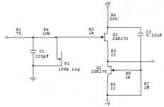
Why hell, that buffer hardly needs any filtering at all. Level is fairly high, the White Cathode Follower topology gives decent supply rejection, and the current demand is small. (I do suspect R6 should be smaller, but don't have time to analyze that now.)
I'd just do this:
Yup, no regulators. Don't need them.
With 10,000 uFd per side and only a few milliAmps power current, that puppy will be quiet and won't respond quickly to utility power fluctuations.
Anybody who feels that EVERYTHING must be regulated... flame off. I'll be off-line for the weekend.
I'd just do this:
An externally hosted image should be here but it was not working when we last tested it.
Yup, no regulators. Don't need them.
With 10,000 uFd per side and only a few milliAmps power current, that puppy will be quiet and won't respond quickly to utility power fluctuations.
Anybody who feels that EVERYTHING must be regulated... flame off. I'll be off-line for the weekend.
Version 2
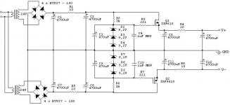
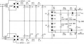
Thanks for all suggestions. Here comes version 2.
I was thinking of using 78xx for a while, but perhaps this is worth a try?
(All eletrolytic caps are 470uF, and all zeners are 9,1V)
Thanks for all suggestions. Here comes version 2.
I was thinking of using 78xx for a while, but perhaps this is worth a try?
(All eletrolytic caps are 470uF, and all zeners are 9,1V)
Beware of the zeners for short circuit protection. Not very effective in your case, very unprecise due to componet variations. It's hardly needed anyway since you have so much R in series. Think also about the low gm a MOSFET has. This creates a rather high output impedance (won't go away with lot's of caps at the output), the voltage will decrease more than if you had used a BJT.
Beware of the zeners for short circuit protection. Not very effective in your case, very unprecise due to componet variations. It's hardly needed anyway since you have so much R in series. Think also about the low gm a MOSFET has. This creates a rather high output impedance (won't go away with lot's of caps at the output), the voltage will decrease more than if you had used a BJT.
I haven't placed the zeners (D9,D10) for short circuit protection. I placed them there to protect the gates at the MOSFET's from exceeding the voltage limit imposed on the Gate - Source rating of the MOSFET.
/Freddie
OK, never thought of it, but of course you should have some proctection.Freddie said:
I haven't placed the zeners (D9,D10) for short circuit protection. I placed them there to protect the gates at the MOSFET's from exceeding the voltage limit imposed on the Gate - Source rating of the MOSFET.
/Freddie
No, in fact only at short circuit. At switch off the body diode of the mosfet will take care of currents backwards.sajti said:It possible during the switch OFF, with high output current.
Sajti
to see "how WELL it works" -- you modulate the positive rail going into the regulator with a signal generator (use a blocking capacitor) and look at the output on a 'scope.
peranders said:
No, in fact only at short circuit. At switch off the body diode of the mosfet will take care of currents backwards.
Unfortunately I lost some mosfets in my premaplifier psu. After I put some protection diodes there was no problem any more.
There is another possibility to protect them: Put diodes between the drain, and the filter caps (C17,18). This diodes normally closed, and they open when the voltage on the filter caps are higher then on the drain of the mosfet. They also helps to discharge the filter capacitors.
One another advice for this type of regulator:
Keep R3, and R7 as low as possible. Someone use 1-100kohms. The regulator will work with them, but there is possibility to get some noise thru the G-D capacitance. This true especially for RF noise.
Sajti
- Status
- Not open for further replies.
- Home
- Amplifiers
- Solid State
- Regulated powersupply, will this work?