You don't need to implement a zener but you need to keep the input/output difference below 40V.
If you can't do this you may want to switch to another regulator like the 723 and make it float.
I guess you may float the 317 as well but there are already positive and negative floating circuits for the 723 from TI that will make your life easier.
Check out the LM317 application hints. That will help a lot.
http://www.ti.com/lit/ds/symlink/lm117.pdf
LM723
http://www.ti.com/lit/ds/symlink/lm723.pdf
I will research "floating" the lm317 but unfortunately i don't have access to the lm723.
")
i don't have access to the lm723.
Why is that?? It's a pretty common reg. Cheaper than bubble gum.
Why is that?? It's a pretty common reg. Cheaper than bubble gum.
Not available in my neck of the woods.
So i made some changes to the original design...
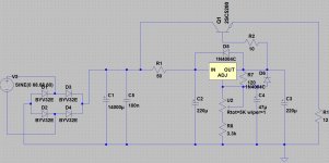
1- I gave up on the lm337 and used two lm317 instead with two NPN transistors (2sc5200), if a dual supply is needed (positive + negative) the two channels can be tied together.
2- The max input-output voltage difference for an lm317 is 40v so i floated the regulator ground via a resistor to allow higher input voltage (tried a zener diode but the reference kept fluctuating ==> zener noise).
3- The reservoir capacitance for each channel is 14000uF consisting of 14 pieces of 1000uf/100V.
4- The resistor on the regulator output to provide constant current draw has been replaced by an LED.
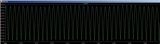
I simulated the circuit in ltspice and attached the output voltage graph, the output @ 58V/5A and as you can see there are some ripple, so the question is....can this ripple be minimized? and if so what is the suggested modifications to the circuit?
PS: I used some models from the YARPS power supply simulation files, thanks a lot Tony.
Best regards.
1- I gave up on the lm337 and used two lm317 instead with two NPN transistors (2sc5200), if a dual supply is needed (positive + negative) the two channels can be tied together.
2- The max input-output voltage difference for an lm317 is 40v so i floated the regulator ground via a resistor to allow higher input voltage (tried a zener diode but the reference kept fluctuating ==> zener noise).
3- The reservoir capacitance for each channel is 14000uF consisting of 14 pieces of 1000uf/100V.
4- The resistor on the regulator output to provide constant current draw has been replaced by an LED.
I simulated the circuit in ltspice and attached the output voltage graph, the output @ 58V/5A and as you can see there are some ripple, so the question is....can this ripple be minimized? and if so what is the suggested modifications to the circuit?
PS: I used some models from the YARPS power supply simulation files, thanks a lot Tony.
Best regards.
Attachments
The circuit is fine but it's not tying the input to the output to take care of the 40V maximum difference.
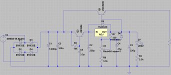
I'd replace the 3904 with something a little tougher like a BD139, and a 36V/1W zenner from the base to the LM317 output.
I'd also replace R2 with a 2K7 to give the BD139 more colector current capability.
Transistor 2SC5200 sounds too weak to me as well being only 1.5A current capable. I'd like a rock solid pass device so my choice would be a darlington 2SD2560, absolutely overkill but keeps the smoke away.
The circuit is fine
Care to get down to the details as fine is a broad defined term.
it's not tying the input to the output to take care of the 40V maximum difference.
The adjust terminal voltage is raised above 0V by a fixed resistor R8 to keep the input-output difference within the regulator parameters same idea as a zener diode actually, there're no need to actually "tying" the input and output together with something.
Transistor 2SC5200 sounds too weak to me as well being only 1.5A current capable. I'd like a rock solid pass device so my choice would be a darlington 2SD2560, absolutely overkill but keeps the smoke away.
The 2sc5200 is a high power transistor with a max. collector current of 17A which is more than needed for this PS and actually more than the 15A for the 2sd2560. May be you meant the base current?
Best regards.
Noise of LM 317 will still remain in the output. Why not use cap multiplier at the output.
Gajanan Phadte
Refer to this link:
Using 3-pin regulators off-piste: part 2
The adjust terminal voltage is raised above 0V by a fixed resistor R8 to keep the input-output difference within the regulator parameters same idea as a zener diode actually, there're no need to actually "tying" the input and output together with something.
The 2sc5200 is a high power transistor with a max. collector current of 17A which is more than needed for this PS and actually more than the 15A for the 2sd2560. May be you meant the base current?
Best regards.
For eg, If your input is around 66V and you set the output at 20V how does R8 keep the input output terminals difference below 40V?
Regarding the 5200 you are correct, I misread the information.
For eg, If your input is around 66V and you set the output at 20V how does R8 keep the input output terminals difference below 40V?
Renesas (formerly NEC) three-terminal regulators application notes...
An externally hosted image should be here but it was not working when we last tested it.
with the resistor it simply won't go to 20V.
Last edited:
Renesas (formerly NEC) three-terminal regulators application notes...
An externally hosted image should be here but it was not working when we last tested it.
with the resistor it simply won't go to 20V.
I agree this set up takes care of Input and Output to ground differential, but does nothing regarding controling Input-Output differential which is to be considered as well. Otherwise you are not really floating the whole thing.
I agree this set up takes care of Input and Output to ground differential, but does nothing regarding controling Input-Output differential which is to be considered as well. Otherwise you are not really floating the whole thing.
Please read the application title carefully "High input, high output voltage circuit" plus if the output doesn't go below 35V and the input is 68V then the input-output differential is definitely under 40V nothing to consider here and please if you're trying to be helpful refer to my real questions in posts 65 and 66 thank you very much.
The cap multipler at the input will only reduce the noise you feed into the input of the LM317.
Isn't that exactly the job of a power supply==>>line regulation...aside from that valuable input what improvements do you suggest on the circuit? Should i keep the 50 ohm current limiting resistor before or after the cap. multiplier? or should i get rid of it altogether? Should the base of the pass transistor connected to the lm317 output with a resistor or without and if a resistor should be used what is the optimum value for it?
Whatever you do, you cannot get rid of the internal circuit noise of LM317 using any measures at the input. The cap multipler at the input will only reduce the noise you feed into the input of the LM317.
Gajanan Phadte
Agree with this. A capacitance bank of some value has to be installed at the regulator's output to reduce noise and output impedance.
Please read the application title carefully "High input, high output voltage circuit" plus if the output doesn't go below 35V and the input is 68V then the input-output differential is definitely under 40V nothing to consider here and please if you're trying to be helpful refer to my real questions in posts 65 and 66 thank you very much.
I'm aware of the high input high output voltage circuit.
And it is OK if you don't set the input/output difference above 40V. But you need to know this circuit has no protective measures against this.
If the trimpot is grossly misadjusted at the first start up you may very well blow up the 317 before even getting to measure anything.
If you implement the zener diode in the location I suggested several posts above you will have a full fail safe design since the zener will only trigger if whatever the reason you push the input/output difference above 36V, thus protecting the 317 in all circumstances.
In my book all this debate is considered help
First I've to have a working power supply within good parameters then we can talk about "fail safe" measures as of now i have to complete the design first and then add fuses and soft starts and all those pretty little things that of course will be helping.
Agree with this. A capacitance bank of some value has to be installed at the regulator's output to reduce noise and output impedance.
In the link i posted there are some measured proof of the effect of a capacitor multiplier prior to the regulator on the output ripple, what measurements or theory do you have to back up your claim?
Best regards.
- Status
- This old topic is closed. If you want to reopen this topic, contact a moderator using the "Report Post" button.
- Home
- Amplifiers
- Power Supplies
- Regulated Negative Power Supply