Hi all,
My apologies if this has been covered (I wasn't able to find this exact question answered anywhere).
I need a +12v/0v/-12v supply. I'm currently using a 30v DC switching power supply, splitting it in two with a couple of 100uF caps and 100k resistors, and then putting each side of that through an LM7812 and an LM7912 respectively. I'm a little concerned about how stable that is and if I may be endangering the LM7*12 regulators (I plan to add some protective diodes, by the way).
My question is would it be better to use an LM7824 to regulate the voltage down to 24v and THEN split that voltage in two (just using caps and resistors, no LM7*12s)?
So in other words, which option is better below?

Thanks for any clarification on this.
My apologies if this has been covered (I wasn't able to find this exact question answered anywhere).
I need a +12v/0v/-12v supply. I'm currently using a 30v DC switching power supply, splitting it in two with a couple of 100uF caps and 100k resistors, and then putting each side of that through an LM7812 and an LM7912 respectively. I'm a little concerned about how stable that is and if I may be endangering the LM7*12 regulators (I plan to add some protective diodes, by the way).
My question is would it be better to use an LM7824 to regulate the voltage down to 24v and THEN split that voltage in two (just using caps and resistors, no LM7*12s)?
So in other words, which option is better below?
Thanks for any clarification on this.
Attachments
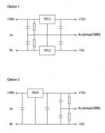
The first one would be better BUT you have to create the virtual GND first, before the regulators. There is an IC for this...100K would not compensate for unbalanced loading between the + and - sides.
Or you could regulate to 24V and then use a 24V to +/-12 DC-DC converter if your power requirements were not too high...would not have common GND with 30V supply.
I did this with for a buffer amplifier for car audio, took the ~12 down to 5V and then back up to an isolated (from car GND) +/-12V. That GND was attached single point to the power amp input ground.
Hope that helps.
Thanks DUG. Just to add, this is for a very simple RIAA preamp. I don't think it would require a lot of current.
The +12v/-12v would power two NE5534s. Would that unbalance the resistors enough to be a problem?
The +12v/-12v would power two NE5534s. Would that unbalance the resistors enough to be a problem?
HI irishstu,
Is there a reason why you are using +/-12 volts? The NE5534 is rated for up +/-22 volts. I would just leave out the extra regulators and use a voltage divider and caps to make +/-15 volts with a virtual ground.
Mike
Is there a reason why you are using +/-12 volts? The NE5534 is rated for up +/-22 volts. I would just leave out the extra regulators and use a voltage divider and caps to make +/-15 volts with a virtual ground.
Mike
Hi Mike, thanks for replying. The preamp circuit I'm using is the "Very Simple Phono Stage" here: RJM Audio - The Very Simple Phono Stage
This is the schematic:
In the construction notes, he mentions that "The phono preamplifier circuit is powered by regulated, low noise, split 12 V supplies."
I'd be very happy to find a simpler solution for the power supply. There's no reason why I have to use a 30v adapter, btw. I could just as easily get a 24v one.
This is the schematic:
An externally hosted image should be here but it was not working when we last tested it.
In the construction notes, he mentions that "The phono preamplifier circuit is powered by regulated, low noise, split 12 V supplies."
I'd be very happy to find a simpler solution for the power supply. There's no reason why I have to use a 30v adapter, btw. I could just as easily get a 24v one.
Last edited:
Hi irishstu,
With that circuit you could use anything from +/-10 volts to +/- 20 volts, no reason to be stuck on +/- 12 volts. I'd recommend using the 30 volt power supply with two 1k ohm/1 watt resistors for the virtual ground, and two electrolytic caps around 470uF to 1000uF of 25 volts or more. You will also need to put a ceramic cap as close to each of the opamp's power supply pins to virtual ground for bypassing, 100nF or larger X7R type would be a good choice.
Mike
The virtual ground works using resistors to divide the voltage, ONLY when the current consumption in the upper and lower half are very similar (and in phase, if variable).
When the current consumption (at any instant) is different in the two halves the capacitors try to supply the difference, but that only lasts for a very short transient.
A low Source Impedance divider (very low values resistors or an active divider circuit) must be used when current consumption is not similar at all instants.
...
or an active divider circuit)
...
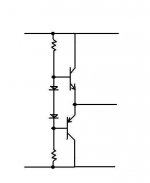
Simplistically like this.
This one will shift a fraction of a volt due to imbalanced loads but if you use a LDO (low drop out) voltage regulator for +/-12V from 30V you should be fine.
(there are also IC's that do this more accurately)
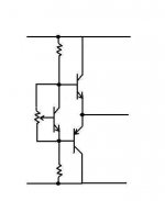
Or a little fancier in -B .jpg.
Attachments
Last edited:
AndrewT and Dug,
He's building a phono preamp. Driving a line input, which are usually 10 kohms or more, with a signal voltage of 2 volts RMS or less, so worst case draw will be less than .0002 mA, and in reality will probably be much less. It won't cause enough modulation of the virtual ground to be a real issue in this case.
Mike
you must take account of capacitance parallel to the load.
If the maximum peak load current is as low as you predict @ ~0.2uApk then expect the capacitance induced peak current to be at least one hundred times that and maybe approaching one ten thousand times that.
If the maximum peak load current is as low as you predict @ ~0.2uApk then expect the capacitance induced peak current to be at least one hundred times that and maybe approaching one ten thousand times that.
AndrewT and Dug,
He's building a phono preamp. Driving a line input, which are usually 10 kohms or more, with a signal voltage of 2 volts RMS or less, so worst case draw will be less than .0002 mA, and in reality will probably be much less. It won't cause enough modulation of the virtual ground to be a real issue in this case.
Mike
What is the part number of the op-amps?
That and output drive will show power supply loading.
🙂
Hi DUG, It's powering two NE5534P op-amps.
Incidentally, I wired it up as per Mike's recommendation at the weekend and it sounds great (to my ears anyway).
What sort of thing should I be listening out for if this is not a suitable way to create the virtual GND?
Again, thank you for all comments. I've already learnt a lot from this thread.
Stu
There are lots of ways of building a buck regulator.
Here's a simple one with an NE555.
555 Negative Voltage Generator
Here's a simple one with an NE555.
555 Negative Voltage Generator
Hi DUG, It's powering two NE5534P op-amps.
Incidentally, I wired it up as per Mike's recommendation at the weekend and it sounds great (to my ears anyway).
What sort of thing should I be listening out for if this is not a suitable way to create the virtual GND?
Again, thank you for all comments. I've already learnt a lot from this thread.
Stu
If you have something that sound good then all you need to do is to measure the two supplies under music conditions.
If they stay stable enough then you are done.
🙂
lm2596
maybe you can try LM2596/2576 to generate negative voltage (12v version or ADJ version)
maybe you can try LM2596/2576 to generate negative voltage (12v version or ADJ version)
Attachments

Last edited:
- Status
- Not open for further replies.
- Home
- Amplifiers
- Power Supplies
- Regulated, dual-voltage power from DC-in