"Screen grid voltage is 1250 V at that graph��.
Yeah I forgot to mention the important part :/
But I have high hopes. I think I can achieve 1A or so.
Also, there are no other graphs with different screen voltages in the datasheet.
I am sure you can't. Remember, you can not have positive g1-voltage.
I got 0.54A at 200V at 200V grid voltage, triode or tetrode connected, didn't make a difference.
I also got 0.43A at 200V at -13V grid voltage, triode or pentode connected.
These were all done after 5 mins of heater warmup time.
Yeah. My transformer can't keep up and hold the 300-330V nominal.
What do you think about the 6S33S-V? It's kinda cheap at about $15.
What do you think about the 6S33S-V? It's kinda cheap at about $15.
Sorry, I meant tetrode connected, not pentode.I also got 0.43A at 200V at -13V grid voltage, triode or pentode connected.
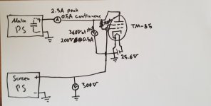
Yes, as the tube is a transmitting pulse tetrode. I tried the current capabilities once triode strapped (plate and screen connected together) and once connected as a tetrode (measured plate current without a cathode and with a separate 200V supply for the screen grid).Tetrode? That means a separate (floating) screen voltage supply. Can you make a drawing?
However, I think I made an error with the screen voltage.
I will get another supply for the screen which will be at 300V and try again and post the results here. I think I made a mistake because I used the existing power lines for plates and screen grids from a tube amplifier (without any tubes in it) and it might be using the same transformer winding (just the plate 350V winding), like using resistors and capacitors to make up another supply for the screens.
If they were separate, the current sinking ability would have been different, right?
Well, I was right. The amp uses one rail for both the plate voltage and screen voltage.Yes, as the tube is a transmitting pulse tetrode. I tried the current capabilities once triode strapped (plate and screen connected together) and once connected as a tetrode (measured plate current without a cathode and with a separate 200V supply for the screen grid).
However, I think I made an error with the screen voltage.
I will get another supply for the screen which will be at 300V and try again and post the results here. I think I made a mistake because I used the existing power lines for plates and screen grids from a tube amplifier (without any tubes in it) and it might be using the same transformer winding (just the plate 350V winding), like using resistors and capacitors to make up another supply for the screens.
If they were separate, the current sinking ability would have been different, right?
I tested the TM-85 with 280V from a completely separate PS and 360V on the plate (at first, and it drops to 200V when the tube is across the main plate PS and the capacitors have discharged). If my multimeter's correct, which it is, it draws a peak of 2.5A when it is first connected and the capacitor is discharging through the tube and then it drops down to 500mA when the transformer is being loaded.
I can confirm the 2.5A with the huge sparks that come off upon contact. I see the same sparks, although a tiny bit bigger, when I directly short the main PS. It has around 600uF of capacitance.
So it seems like the tube can easily handle a few amps, provided that we don't exceed the max plate dissipation of 60W.
Connect g1 to cathode. This shows the maximum plate current you can have. The present schematic is unrealistic.
Connect g1 to cathode. This shows the maximum plate current you can have. The present schematic is unrealistic.
I got 0.45A @ ~200V triode connected, grid connected to the cathode through a 470k resistor.
- Home
- Amplifiers
- Power Supplies
- Regulated 0-250V Vacuum Tube Based Power Supply
