Hi,
You're doing fine. Now go back to the references in Post #18.
Regards,
Hmmm and I thought I was ready!... anyway: here it is! Are we there yet? 😀
Attachments
Hi erik1971,
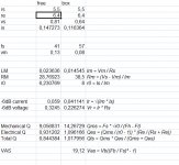
Looks like you got some values 🙂. Both references mention a check of Fl-Fh-Fs, I assume you did this. You still will have to find Le, and plug the values into a modelling program, a lot of people use Hornresp, by David McBean. Once you get the hang of it it's quite easy to use and very powerful.
Regards
Attachments
Hi erik1971,
Looks like you got some values 🙂. Both references mention a check of Fl-Fh-Fs, I assume you did this. You still will have to find Le, and plug the values into a modelling program, a lot of people use Hornresp, by David McBean. Once you get the hang of it it's quite easy to use and very powerful.
Regards
Yeps, double checkrd... Le??? Are you just making up things to keep me busy?
Busy - Busy
Hi again,
You got me, I invented the concept of Le just to keep you busy. ROFL Well, you're not the only busy beaver, another day in the life of a pay slave.
I typed your values into Hornresp and used the volume and duct dimensions from the previous Boxplot simulation. Once you get into Hornresp you'll find that the biggest problem with it is not to get addicted to it.
Regards,
Attachments
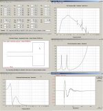
hmm.. normally Iam pretty sensitive to addictions... but I do not feel anything yet... To be completely honest, after studying the attached picture, I still have no clue wether it says: "Do not build that speaker in that enclosure", or "briljant plan, go ahead!"😕
The object is to have a ~flat in-room response from at least 20-20 kHz at the listening position(s), but this goal is often too costly in room space and/or budget, so a higher tuning to roll off the bass is often adopted. Also, depending on the type of music and playback system you listen to, it may be a waste of $$$/effort, i.e. most recorded music only needs a 35-40 Hz tuning (Fb).
From this we see that ideally one needs to map the room's acoustics in general and its gain curve in particular to determine what the 'sub' woofer's response should be, i.e. how flat it should be down to 'x' frequency before rolling off and how fast (steep) this slope should be.
Since most DIYers won't measure it for whatever reason, one can choose a published average or just build biggest, flattest, lowest tuned 'sub' woofer and either fiddle with its tuning and/or EQ it ~flat in-room if it sounds too 'boomy'/'one note'.
Looking at Oliver's first plot then, we see it's flat down to ~35 Hz before rolling off, so one most folks would build, but it doesn't show the effect that inductance can have on the response, so in the upper right corner plot of his second sim, he uses the same specs, design as the first one except he included a very high 7.0 mH Le value to highlight its effect on the response which as you can see creates a very tall 'bump' in the response which most folks would consider a fairly 'boomy' bass with no deep bass to speak of if there's any in the recording since it's so rolled off below ~50 Hz.
In a car with its typically high cabin gain due to being such a small 'room', this alignment would probably perform OK, but in a typical HIFI/HT app it would sound more like a cheap boom-box with no deep bass, so normally not acceptable unless tuned higher and even then it would tend to sound 'slow' compared to the mains if not XO'd down at or below its ~70 Hz peak due to the inductance acting as an electrical brake on its transient response.
Anyway, hopefully you now understand why the need to know a driver's Le and not just the basic Fs, Vas, Qts specs. From this we also can assume that if a manufacturer doesn't publish it along with the others, it's because it's unacceptably high for most apps other than cars.
GM
Anyway, hopefully you now understand why the need to know a driver's Le and not just the basic Fs, Vas, Qts specs. From this we also can assume that if a manufacturer doesn't publish it along with the others, it's because it's unacceptably high for most apps other than cars.
GM
Yep it is! Next mission: to find Le! And thanks a lot for the long and clear explanation. It was not that long ago a speaker was just a box, driver and air vent to me!
From what I understand it is: the voice coil inductance measured in millihenries (mH) at 1,000 Hz.
Any tips on how to do this since my multimeter does not seem to do milihenries!
You're welcome!
Well, what I do is measure Re and again at some frequency (Zxo @ Fxo) well away from Fs, usually at the desired XO point, but 1 kHz is fine if you want to compare to published specs, then:
Le (mH) = 1000*(Zxo^2-Re^2)^0.5/(2*pi*Fxo)
If a driver has a published impedance plot then, it can be quickly calculated close enough for simming comparison purposes.
GM
You're welcome!
Well, what I do is measure Re and again at some frequency (Zxo @ Fxo) ...
GM
would that be free air or in the box?
- Status
- Not open for further replies.
- Home
- Loudspeakers
- Subwoofers
- refitting logitech z-2300 sub into different cabinet: room for improvement?