TNT, kindly help me understated where I am wrong. I am not challenging you but I am unable to understand that with the final sampling rate of 64x (2.822MHz) why the following principle is not applying to this DAC.
From http://www.analog.com/media/cn/training-seminars/tutorials/MT-017.pdf
"For instance, oversampling is common in digital audio CD
players, where the basic update rate of the data from the CD is 44.1 kSPS. Early CD players used
traditional binary DACs and inserted "zeros" into the parallel data, thereby increasing the
effective update rate to 4-times, 8-times, or 16-times the fundamental throughput rate. The 4×,
8×, or 16× data stream is passed through a digital interpolation filter which generates the extra
data points. The high oversampling rate moves the image frequencies higher, thereby allowing a
less complex lower cost filter with a wider transition band. "
It applies here! Only the terminology in the area is babylonian 😛
The "less complex lower cost filter with a wider transition band" are the analog filters. It is expensive and complicated to build a good analog brickwall filter.
This applies also here, the DAM has only an very simple analog filter, an RC-element.
The high oversampling rate, per se, does not remove the higher image frequencies. Only in combination with the "digital interpolation filter" (which is a low pass filter) you get "rid" of the higher images. The higher the oversampling rate is the better filters you are able to design.
Now we are at the point that we have to choose the digital filter.
As we have not infinite oversampling, computing resources etc, we need to make some compromises. And the good thing about the DAM is we can design the filter ourselves and are not limited to the manufacturers filter (or filters).
"The high oversampling rate moves the image frequencies higher"
- But this is only for whole Fs band images - that would be 44,1 Khz bands for example 44,1-88,2. But the first alias spectrum, 22,05-44,1 kHz (in this case) will never be "moved" irrespectivly of oversampling rate. Is this correctly understood?
//
- But this is only for whole Fs band images - that would be 44,1 Khz bands for example 44,1-88,2. But the first alias spectrum, 22,05-44,1 kHz (in this case) will never be "moved" irrespectivly of oversampling rate. Is this correctly understood?
//
Last edited:
"The high oversampling rate moves the image frequencies higher"
- But this is only for whole Fs band images - that would be 44,1 Khz bands for example 44,1-88,2. But the first alias spectrum, 22,05-44,1 kHz (in this case) will never be "moved" irrespectivly of oversampling rate. Is this correctly understood?
//
What I've seen while messing around with the DAM filters is that the spacing between images always remains at fs/2 regardless of oversampling rate. If you oversample 44.1Khz audio at x8 you end up with a 352.8khz bandwidth. The original audio information remains between 0-22050Hz then 7 additional images reflecting at 22050kHz intervals. There are non-mirrored images at 44.1, 88.2 and 132.3kHz, and mirrored images at 22.05, 66.15, 110.25 and 154.35kHz.
I see no evidence that oversampling - in and of itself - increases the size of the transition band or increases the spacing of any of the images.
As I understand it it can if interpolation is used but not when doing 0 stuffing. But not even interpolation will move 22-44 I think.
So is the filter really helped by OS? I still belive so as OS decreases the energy of the images. I suppose also 22-44 or it would be useless (as I see it)
//
So is the filter really helped by OS? I still belive so as OS decreases the energy of the images. I suppose also 22-44 or it would be useless (as I see it)
//
Last edited:
Got my amanero and this DAC playing with a alps pot for volume and a lab PSU to make do.....
Transparency is uncanny ...from the very little testing i did it is easy to see that it handles hardrock to classical with equal ease...voices and instrumentals are gorgeous ( Tried some mp3s that ZM posted on his blog and to my surprise they sounded great...yes mp3s) ....and i was listening out of the balanced outputs with my UGS and a BJ2....looking forward to experimenting with a discreet balanced buffer.....🙂
All files were FLAC except those above ...i will test genuine highres files including DSD later.
I used my laptop with foobar....did i mention it was dead silent between tracks even with UGS at max ?....
Cannot help but compare to my BIII with SEN outputs...................it's like comparing great art.....it's all great but different....
After all fun is what it's all about.....and great music.
Last edited:
I would like to revoke or at least reohrase my powering idea. SMPS is considerable worse than batteries. Its eveident listening over high resolving speakers. I will filter my SMPS via a Kentokeans Capacitor Multiplier.
Had some really nice music moments tonight using the DAM. It has qualities for sure.
//
Had some really nice music moments tonight using the DAM. It has qualities for sure.
//
As I understand it it can if interpolation is used. But not even interpolation will move 22-44.
So is the filter really helped by OS? I still belive so as OS decreases the energy of the images. I suppose also 22-44 or it would be useless (as I see it)
//
My guess is that much of the information on DAC filters, especially from the 90's, is focusing on the reduced requirements for analog filtering, and treats the digital filter and oversampling DAC as a "black box".
Energy is definitely reduced. If you upsample x8 with zero insertion, you end up with one sample with original value/energy and seven zero value samples. This means the up sampled data has 1/8th the energy of the original. If you don't filter as in NOS, the up sampled data contains 7 images and the baseband audio, so the up sampled file contains the same level of energy as the original audio. You can't apply additional gain to the NOS audio because it will clip. Once you filter the images, you are left with 1/8th the energy, and you need to apply x8 gain to bring it back to original.
Perhaps the reduced energy level of the images makes filtering more effective, but for filter design purposes it appears that we are still dealing with a 2kHz transition band for 44.1kHz audio.
You need to do some testing and put theory into practice. I suspect what you'll find is that what is held as "common knowledge" is not supported in fact.
I say that on the basis of having done some tests with software upsampling (octave and SoX) and with measuring the output of the DAM running a NOS filter for FIR1 . The result is the same - images evenly spaced at fs/2 intervals.
Last edited:
My guess is that much of the information on Audio filter, especially from the 90's, is focusing gone the reduced requirements for analog filtering, and treats the digital filter and oversampling DAC as a "black box".
...appears that we are still dealing with a 2kHz transition band for 44.1kHz audio.
Spot on x2!
//
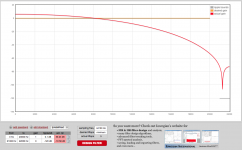
Try to design (e.g. with T-filter) a low pass filter with 0-20kHz passband, with at most 0.1dB pass-band-ripple, and stop band -120dB beginning at 21kHz.So is the filter really helped by OS? I still belive so as OS decreases the energy of the images. I suppose also 22-44 or it would be useless (as I see it)
//
Try to do that with a sample rate of 44kHz and one with 8x44kHz. You will see the usefulness of oversampling 🙂
zfe - please explain further, a drawing would porbbaly be helpful - would really like to get this full out.
//
//
Sorry to go backwards a tad but I'm having trouble getting a lock with my Amanero to the DAM1021.
The amanero is a second hand from someone on this forum and I had difficulty pulling out the pins that was used. I checked and realized the trace for bclk at the pins was broken while removing the old pins - I have since been able to tap it straight from the chip.
Right now, the Data and Bclk lines are at 3.26V... but my fsclk (or LRCK) is only reading 1.63V (even straight out of the chip)... is this normal? I'm asking because this value is the same straight out from the CMOS, but I'm suspecting that this is the cause of my problems getting a lock...
Would be great if anyone had any ideas on what could be causing the lower voltage that I suspect is the issue as well.
Thanks in advance for any help!
As per zfe's suggestion....
So it's virtually impossible to design something satisfactory at 44.1, but trivial at 44.1x8.
It seems the fact that the stop band is 155400Hz at 44.1x8 rather than 1050Hz at 44.1 allows for a more optimal solution to the filter design.
So it's virtually impossible to design something satisfactory at 44.1, but trivial at 44.1x8.
It seems the fact that the stop band is 155400Hz at 44.1x8 rather than 1050Hz at 44.1 allows for a more optimal solution to the filter design.
Attachments
Last edited:
Sorry to go backwards a tad but I'm having trouble getting a lock with my Amanero to the DAM1021.
The amanero is a second hand from someone on this forum and I had difficulty pulling out the pins that was used. I checked and realized the trace for bclk at the pins was broken while removing the old pins - I have since been able to tap it straight from the chip.
Right now, the Data and Bclk lines are at 3.26V... but my fsclk (or LRCK) is only reading 1.63V (even straight out of the chip)... is this normal? I'm asking because this value is the same straight out from the CMOS, but I'm suspecting that this is the cause of my problems getting a lock...
Would be great if anyone had any ideas on what could be causing the lower voltage that I suspect is the issue as well.
Thanks in advance for any help!
are you reading with a multimeter or scope?
1.6ish can be a signal
are the other i2s been measured juring playback or not,?
cause I think they read 3.3ish while not playing
are you reading with a multimeter or scope?
1.6ish can be a signal
are the other i2s been measured juring playback or not,?
cause I think they read 3.3ish while not playing
Hi Nige2000,
Thanks for helping!
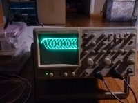
The earlier readings were done with a multimeter. I haven't used a scope in ages but did manage to get some waveforms after fiddling around. Not sure if they help... for some reason (with the exception of FSCLK), I can only get something to show with audio playing.
First image - BCLK
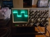
Second image - FSCLK
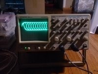
Third image - DATA
I should probably state how I connected it
Amanero ---> DAM1021
BCLK -> BCLK
FSCLK -> LRCK
DATA -> DAT
3.3V -> ISO 3.3V
Because I was using twisted pairs each of the connections have a connection with ISO GND (don't think this will cause a problem?)
Attachments
Hi Nige2000,
Thanks for helping!
The earlier readings were done with a multimeter. I haven't used a scope in ages but did manage to get some waveforms after fiddling around. Not sure if they help... for some reason (with the exception of FSCLK), I can only get something to show with audio playing.
First image - BCLK
Second image - FSCLK
Third image - DATA
I should probably state how I connected it
Amanero ---> DAM1021
BCLK -> BCLK
FSCLK -> LRCK
DATA -> DAT
3.3V -> ISO 3.3V
Because I was using twisted pairs each of the connections have a connection with ISO GND (don't think this will cause a problem?)
Hi Nige,
You helped me to spot the error. I tapped the wrong pin from the CMOS! Going to try to fix it now and try again.
Best,
A low priority firmware request for Soren,
Now that we'll have multiple filter options selectable by serial communication in the future, could the firmware sleep serial port immediately after a filter change. I'm asking this because you mentioned making serial port sleep after a period of inactivity to prevent noise.
Question for Arduino people:
Can the serial port be controlled by one of those 5V boards (Leonardo?). 3.3V isn't enough to wake the serial port up. Is this the way Arduino works, like a PC host?
A low priority firmware request for Soren,
Now that we'll have multiple filter options selectable by serial communication in the future, could the firmware sleep serial port immediately after a filter change. I'm asking this because you mentioned making serial port sleep after a period of inactivity to prevent noise.
That is pure hardware on the real RS-232 port, it disables then small DC-DC converter on it when nothing is connected.
Question for Arduino people:
Can the serial port be controlled by one of those 5V boards (Leonardo?). 3.3V isn't enough to wake the serial port up. Is this the way Arduino works, like a PC host?
Next firmware release will enable the serial port on the isolated side, at 3.3V digital levels....
Next firmware release will enable the serial port on the isolated side, at 3.3V digital levels....
Just when I was wandering why those pins didn't work..
This is excellent news! 😀
Question for Arduino people:
Can the serial port be controlled by one of those 5V boards (Leonardo?). 3.3V isn't enough to wake the serial port up. Is this the way Arduino works, like a PC host?
(for the record, since Soren essentially answered this a couple of posts up)
The Arduino does not support "real" RS-232 communication but it is easy to implement an RS-232 driver using an inexpensive IC and 4-5 caps.
So far in my attempts to get reliable communication between my controller and the DAM I've built 3 such circuits, but they all excibit the same behavior (unreliable operation). I'm not saying that it's the DAM's fault, I really don't know, but I will be a happy person when the isolated 3.3V serial pins get enabled.
Note: You will still need an Arduino with 3.3V I/O pins (like the Due) or level conversion for the older boards.
That is pure hardware on the real RS-232 port, it disables then small DC-DC converter on it when nothing is connected.
Next firmware release will enable the serial port on the isolated side, at 3.3V digital levels....
According to the data sheet of the isolators one can configure the input side for up to 5V operation (VCC1=5v) and the low side to 3.3V (hard wired). The isolators on the board allow this mode? I ask because Arduinos like to operate at 5V especially if driving a 5V display. This will also allow interfacing to old CD players which I believe operate their I2S at 5V (or equivalent serial interface)
dimdim, I guess I won't have to wait until you solve the rs232 issue 🙂.
Thanks!
Last edited:
- Home
- Vendor's Bazaar
- Reference DAC Module - Discrete R-2R Sign Magnitude 24 bit 384 KHz