Please Sören, two PLL modes - 1) Movie and 2) Music.
//
That is actually a great suggestion.
Sören
Where would best place be for features or suggestions for the dac2541?
OK on this thread?
Where would best place be for features or suggestions for the dac2541?
OK on this thread?
Sören
Where would best place be for features or suggestions for the dac2541?
OK on this thread?
The dac2541 is NOT a DIY product, so it's not something I intend to discuss here.... You're always welcome to email me suggestions, but please note that the hardware is done, production have started, but work is still being done on the firmware.... But basically it's an updated dac1541, with same features, in fact, the casing is reused....
There will NOT be a "movie" / "music" selection, that would be an unneeded distraction and would require a switch to control.... But the PLL/FIFO logic will be updated.
I am considering what to do with the DIY/OEM boards, thinking about reducing the three boards to two, but it's not that easy as they're quote different.... Maybe I'll just update all three....
OK... It would be nice if the PLL could adapt to how stable the incoming clock seem to be and gradually rely on it and adopt an decreasingly need to adjust the local clock - to the point that we see adjustments on an hourly level... colder in the night... a little adjustment ;-)
And to keep its "cool" between tracks etc. i.e. only sync loss would trigger a complete reset of the adjustment process and go into "wide" (movie) mode.
//
And to keep its "cool" between tracks etc. i.e. only sync loss would trigger a complete reset of the adjustment process and go into "wide" (movie) mode.
//
Hi guys, I'm writing here cause I don't know where I could correctly post this question. It regards the xmos board which collect signal from usb and sends it to the I2S input of my dam1021 board. I built a Reflektor-D to feed it and I setted it to output 3.3v. like many of you had already done, I will use it to feed the xmos chip and the isolated input of dam1021. Unluckily, it turned out the the shunt reg outputs 3.2v instead of 3.3v. Sören already said me the it's not a problem for the dam1021 board, but now I thinking to the xmos board. Could it be feeded the same with 3.2v instead of 3.3? I'm scratching my head...
Thank you,
Gaetano.
Thank you,
Gaetano.
The reflektor can be made to output 3.3V by changing a led.
But I wouldn' t power both the dam and the xmos from the same regulator.
But I wouldn' t power both the dam and the xmos from the same regulator.
Could it be feeded the same with 3.2v instead of 3.3?
It can, but as vgeorge said, it is not a great idea. Sharing the same PS will render the isolation ineffective. You need not only 2 regulator boards but two completely independent power supplies with separate transformer windings.
I was convinced it was important to keep separate supplies just for the dam board and its isolated input, cause these two sections must not get in contact. Why should it be avoided to use a common supply for the xmos and the isolated I2S? I have seen instead, if I am not wrong, other builds with a common supply at these two levels.The reflektor can be made to output 3.3V by changing a led.
But I wouldn' t power both the dam and the xmos from the same regulator.
Am I missing something?
Thank you,
Gaetano.
PS: btw, my concern was about my build of the Ref-D, which I setted to output 3.3v and it turned out to output only 3.2. Are these volts enough to supply the xmos?
I was convinced it was important to keep separate supplies just for the dam board and its isolated input, cause these two sections must not get in contact. Why should it be avoided to use a common supply for the xmos and the isolated I2S? I have seen instead, if I am not wrong, other builds with a common supply at these two levels.
Am I missing something?
Thank you,
Gaetano.
PS: btw, my concern was about my build of the Ref-D, which I setted to output 3.3v and it turned out to output only 3.2. Are these volts enough to supply the xmos?
Just I prefer to keep the power supplies separated. I will work with common supply without problems. Just be sure to calculate the current consumption of the dam and the xmos together for the reflektor.
I was convinced it was important to keep separate supplies just for the dam board and its isolated input, cause these two sections must not get in contact. Why should it be avoided to use a common supply for the xmos and the isolated I2S? I have seen instead, if I am not wrong, other builds with a common supply at these two levels.
Am I missing something?
Thank you,
Gaetano.
PS: btw, my concern was about my build of the Ref-D, which I setted to output 3.3v and it turned out to output only 3.2. Are these volts enough to supply the xmos?
The XMOS interface and the outside 3.3V power for the isolators should really be powered by the same source. And as pure digital power, the quality is not that critical, you can use the regulated USB Power, just any 5V to 3.3V linear regulator....
So I can consider not that wrong to use one Reflektor-D module to feed both the xmos board and the dam isolators...The XMOS interface and the outside 3.3V power for the isolators should really be powered by the same source. And as pure digital power, the quality is not that critical, you can use the regulated USB Power, just any 5V to 3.3V linear regulator....
The dac2541 is NOT a DIY product, so it's not something I intend to discuss here.... You're always welcome to email me suggestions, but please note that the hardware is done, production have started, but work is still being done on the firmware.... But basically it's an updated dac1541, with same features, in fact, the casing is reused....
There will NOT be a "movie" / "music" selection, that would be an unneeded distraction and would require a switch to control.... But the PLL/FIFO logic will be updated.
I am considering what to do with the DIY/OEM boards, thinking about reducing the three boards to two, but it's not that easy as they're quote different.... Maybe I'll just update all three....
Hi Sören,
Are you still considering to release a ADC?
Apparently, there are no offerings available on the market so this nische is up for you to grab.
Pro and end-user market may have some requirements in common such as low S/N analog balanced inputs and both I2S and AES outputs.
End-users needs 2-channel input where the Pro market ofcourse require multiple channels.
/Lars
Hi Sören,
End-users needs 2-channel input where the Pro market ofcourse require multiple channels.
/Lars
Not really, the best mastering AD converters still come as 2-channel units.
I am also convinced there is a market. These days, a new purely-PCM AD-converter will set you back a minimum of 7000 EUR.
I built a custom balanced output for the DAM1021 based on inverting NJM5532DD (best sounding dual op amp in mine and many other studio people's opinion).
It's really obvious in comparison how bad the on-board balanced output sounds. Squashed dynamics, concealed details, a blunted and at the same time stressed high end.
Though actually rather simple, it took quite a lot of tweaking by ear (many recordings with a high end AD converter and comparing the output to the original file) to get it to sound as good as it is now. Needs a good power supply, of course.
Drawbacks to my output stage are higher noise and more DC offset than the on-board solution. The latter is taken care of by the blocking caps implimented in most amplifiers, of course.
I will use this output stage in my 32 channel DAC for studio use. If anyone is interested, I can post the schematic.
If anyone is interested, I can post the schematic.
Please do.
It is really simple, with a little more gain than the on-board solution. The inverting op amp configuration sounds much cleaner to my ears, even though a non-inverting solution can in theory measure equally low in THD (except for the very high end of the spectrum with the 5532). The 22pf caps in the feedback path should be NPO/COG, the 100nf decoupling caps X7R and the electrolytics a standard type (not low-ESR, since their inherent resistant increases stability). Coupling caps should be reasonably close to the op amp pins. Don't use more decoupling (especially not rail-to-rail, no matter what Douglas Self writes, I don't think it sounds good with the 5532 and I've encountered oscillation with other op amps this way). The usual caveats with regards to board design, grounding etc. apply.
C1,C5,R7,R4 can be left out if some DC can be tolerated by the following stage.
Phase and frequency response deviations are inaudibly low. I couldn't detect any stability problems.
The resistor selections result in an elevated noisefloor, but it sounds better this way to my ears. Noise is still much lower than with vinyl, a studio tape machine with noise reduction, 16 Bit CD audio etc.
Use a linear +/- 15-18 VDC PSU.
Attachments
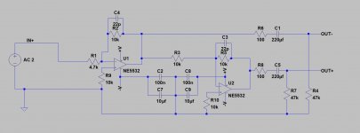
Or you could use the new TI opa1656, those are good, see the opa1656 thread.... In my opinion, the 5532 is pretty old....
Like the design I use in the new dac2541. This circuit have only one opamp in the path of each of the + and - output. You will need to double the resistors for the dam1021, to match the R-2R resistor networks, as the dac2541 have half the output impedance of the R-2R network.
The opamps can take up to +- 15V, you would need to change the decoupling caps to match. But it will work just fine on +- 5V
Attachments
The inverting op amp configuration sounds much cleaner to my ears
Agree. It was the only way to obtain reasonable sound out of the old 5534s in the eighties.
Thank you for sharing your thoughts and the design.
- Home
- Vendor's Bazaar
- Reference DAC Module - Discrete R-2R Sign Magnitude 24 bit 384 KHz