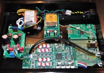
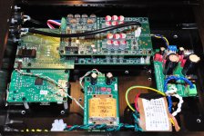
Anyone see anything obviously wrong with this setup? This is a balanced dual-mono configuration. I'm using Normundss' board to parallel the two dam1021s, and also use the Raspberry Pi as input. That "middle" power supply with the Triad transformer is the power supply to the input board. The two dam1021 boards are powered by the DIYINHK LT3042 regulator board.
This config was working perfectly until I made the following changes today:
So what's wrong? The top board is very inconsistent. Sometimes it works just fine. Other times, I get intermittent obvious distortion. This distortion isn't constant, it seems to be tied to certain frequencies (or at least certain musical passages). The worse case is very loud popping, almost like there's an intermittent direct short to the output (as it makes the drivers visibly move). I pull the amp power immediately when this starts happening.
It's definitely the top board. And that doesn't make any sense to me, because it's only the bottom board I messed with today. If the reduced power supply voltage were the issue, I'd think it would affect both boards.
Any ideas on what might be wrong?
This config was working perfectly until I made the following changes today:
- Add VREF caps to the bottom board. The top board already had the same VREF caps.
- Change R-Core transformer and voltage into dam1021. Original xformer had dual 15V secondaries capable of 1A each. The LT3042 was set for +/-12V operation. Now the transformer has 9V/0.8A secondaries, and the regulator is set for +/-9V operation.
So what's wrong? The top board is very inconsistent. Sometimes it works just fine. Other times, I get intermittent obvious distortion. This distortion isn't constant, it seems to be tied to certain frequencies (or at least certain musical passages). The worse case is very loud popping, almost like there's an intermittent direct short to the output (as it makes the drivers visibly move). I pull the amp power immediately when this starts happening.
It's definitely the top board. And that doesn't make any sense to me, because it's only the bottom board I messed with today. If the reduced power supply voltage were the issue, I'd think it would affect both boards.
Any ideas on what might be wrong?
Attachments
This config was working perfectly until I made the following changes today:
- Add VREF caps to the bottom board. The top board already had the same VREF caps.
- Change R-Core transformer and voltage into dam1021. Original xformer had dual 15V secondaries capable of 1A each. The LT3042 was set for +/-12V operation. Now the transformer has 9V/0.8A secondaries, and the regulator is set for +/-9V operation.
So what's wrong? The top board is very inconsistent. Sometimes it works just fine. Other times, I get intermittent obvious distortion.
The obvious suspects are:
1) Bad connections/solder joints caused by mechanical stress while assembling/disassembling the setup.
2) Are you sure the bottom board VREF caps are not touching the bottom of the top board? Can't see it in the photos.
2) Are you sure the bottom board VREF caps are not touching the bottom of the top board? Can't see it in the photos.
Definitely sure on that front. There's at least a whole cm of clearance between the bottom VREF caps and the top board (I can get my finger tip in between).
At any rate, I did some more listening/testing: it seems the "scratchiness" was sometimes coming from both speakers. So that made me think power supply issue.
I just put the original 15V/1A xformer back, and switched the regulator to +/-12V mode. So far it seems the problem is gone.
I could previously consistently replicate the distortion/scratchiness on one part of one song. At around 0:58 of the first song on DG's recording of Dvorak's 9th conducted by Karajan, there are some "dramatic" chords alternating between strings and horns. Whenever the horns sounded, I got the noise on either or both speakers.
With 15VAC+12VDC, I've listened to that passage multiple times now, and been listening for the last 40+ minutes, no weird sound artifacts.
So, it appears to be a power supply issue. I can think of a couple things: (1) 9VAC isn't enough headroom for 9VDC for the DIYINHK LT3042 board. Someone above mentioned it should work, but the board's silkscreen actually says use AC voltage that is desired DC voltage + 3. (2) Transformer couldn't supply enough current. I'd think 0.8A should be more than enough for two dam1021 boards though.
I'm using a 30VA Rcore transformer 2 x 9V and same regulator. The input voltage to the regulator is 11,2V AC. I'm powering 1 board. Works fine. I tested the regulator @ 300ma and still get 9V output.
So almost same setup, but powering 1 board.
Make sure to isolate the dac, the corner holes are all connected to ground so i use plastic screws.
Try to measure the regulator outputs not connected to the dac but with a 30 ohm load (300mA), do you still get 9 Volts?
So almost same setup, but powering 1 board.
Make sure to isolate the dac, the corner holes are all connected to ground so i use plastic screws.
Try to measure the regulator outputs not connected to the dac but with a 30 ohm load (300mA), do you still get 9 Volts?
Last edited:
I'm using a 30VA Rcore transformer 2 x 9V and same regulator. The input voltage to the regulator is 11,2V AC. I'm powering 1 board. Works fine. I tested the regulator @ 300ma and still get 9V output.
So almost same setup, but powering 1 board.
Make sure to isolate the dac, the corner holes are all connected to ground so i use plastic screws.
Try to measure the regulator outputs not connected to the dac but with a 30 ohm load (300mA), do you still get 9 Volts?
You're powering 2 boards so 2 x 180mA = 360mA (positive rails). Try a load of 22,5 ohm (400mA). 5W resistor should work.
Last edited:
I'm using a 30VA Rcore transformer 2 x 9V and same regulator. The input voltage to the regulator is 11,2V AC. I'm powering 1 board. Works fine. I tested the regulator @ 300ma and still get 9V output.
Interesting. Does your R-core have only 2x9V secondaries, or does it have more secondaries as well? If the former, then I suspect your transformer has way more secondary current than the one I was using.
Make sure to isolate the dac, the corner holes are all connected to ground so i use plastic screws.
Yup, I'm using only plastic screws.
Try to measure the regulator outputs not connected to the dac but with a 30 ohm load (300mA), do you still get 9 Volts?
...
You're powering 2 boards so 2 x 180mA = 360mA (positive rails). Try a load of 22,5 ohm (400mA). 5W resistor should work.
I'll have to buy some power resistors before I can do that test.
I was thinking, though, perhaps I could use my DMM in ammeter mode with my current (working) 15VAC/12VDC setup. I could measure DC current between regulator and DAC boards; and also measure AC current between transformer and regulator. The idea is to see what kind of current is actually being pulled. However, I have a super-cheap DMM, not sure if it's fast enough to actually show peak current bursts...
@Søren: what kind of behavior would you expect from the dam1021 boards if supply voltage drops below 9VDC? How about if the voltage is constant but the supply can't provide enough current?
Interesting. Does your R-core have only 2x9V secondaries, or does it have more secondaries as well? If the former, then I suspect your transformer has way more secondary current than the one I was using.
However, I have a super-cheap DMM, not sure if it's fast enough to actually show peak current bursts...
30VA R-Core only 2x9V
I think the current is pretty much the same, independent of load & voltage. So no bursts. In your case it should be 2*180mA positive, 2*60mA negative.
What voltage do you measure on the input of the 2 dac's?
Hi, I have not found much info online about Raspberry Pi and Soekris combination.
Does the Soekris work fine with the RPi audio coming from the I2S interface without a proper clock? My fear is the lack of two oscillators in the DAC to get all the sample rates (is it 44.1 and 48 compatible?).
Thank you
Does the Soekris work fine with the RPi audio coming from the I2S interface without a proper clock? My fear is the lack of two oscillators in the DAC to get all the sample rates (is it 44.1 and 48 compatible?).
Thank you
Hi, I have not found much info online about Raspberry Pi and Soekris combination.
Does the Soekris work fine with the RPi audio coming from the I2S interface without a proper clock? My fear is the lack of two oscillators in the DAC to get all the sample rates (is it 44.1 and 48 compatible?).
Thank you
DAM has one programmable oscillator that is automatically adapted to match the incoming rates.
//
Sœren actually mentioned in an earlier post that he was considering (or maybe even planning?) releasing a RPi specific addon board with the DAM. I can't remember the exact post though.
For myself that would be the perfect match and I am in the middle of planning the build right now.
For myself that would be the perfect match and I am in the middle of planning the build right now.
thank you. i understand this means it plays 44.1 AND 48 nicely even if the clock is 44.1 only.
great, an extra to the DAM, i would love to see more info on this as well. going to search the thread. thank youSœren actually mentioned in an earlier post that he was considering (or maybe even planning?) releasing a RPi specific addon board with the DAM. I can't remember the exact post though.
For myself that would be the perfect match and I am in the middle of planning the build right now.
Well it's actually not an addon to the current DAM, see:great, an extra to the DAM, i would love to see more info on this as well. going to search the thread. thank you
Sounds great. @soekris what kind of input/output interfaces will it have? Thank youJust for info, I'm working on a dam version to fit directly onto a Raspberry Pi, with flexible power supply, "ATX" style power management and direct display connection. Will also have alternative I2S connector for odroid.
No soldering needed, perfect for making a R-2R RaspTouch....
Hi, I have not found much info online about Raspberry Pi and Soekris combination.
Does the Soekris work fine with the RPi audio coming from the I2S interface without a proper clock? My fear is the lack of two oscillators in the DAC to get all the sample rates (is it 44.1 and 48 compatible?).
As others have said, yes, it works great. See my recent post (#6021) where I supplied pictures of a Soekris dam1021 + RPi build.
I'm using the Normundss input board to integrate the RPi with my dam1021 boards. This is a balanced dual-mono setup. You don't need the input board, but it makes the wiring easier as well as neat and tidy (particularly for two dam1021 boards).
For a single dam1021, you can easily get away with simple jumper wires to connect the Rpi to the DAC.
Thank you so much!As others have said, yes, it works great. See my recent post (#6021) where I supplied pictures of a Soekris dam1021 + RPi build.
I'm using the Normundss input board to integrate the RPi with my dam1021 boards. This is a balanced dual-mono setup. You don't need the input board, but it makes the wiring easier as well as neat and tidy (particularly for two dam1021 boards).
For a single dam1021, you can easily get away with simple jumper wires to connect the Rpi to the DAC.
Ok, a little more on the dam1231, the Raspberry Pi version:
Will fit directly on top of RPi. The dam1231 is a little larger, but will fit most cases as there usually are extra space.
Physical compatible with the AudioPhonics RaspTouch and other cases from them.
Inputs are I2S from RPi GPIO connector, extra I2S for t.ex. Odroid, SPDIF Coax and Toslink.
Outputs are RCA single ended, buffered by LT1815.
Builtin power management like RaspTouch. Power from RPi or external power though DC plug.
Pass though connector for RPi SPI display. Connector for volume control and IR receiver.
Should be supported already by some software packages as a dam1021, but will require more software support for all functions.
Just got the prototype PCB's, will be mounted in about two weeks. Firmware should be easy and quick as it's just a variation of existing boards.... So I should have production boards around year end, assuming no unexpected surprised..... Estimated pricing around USD 260 / EUR 235 for a -02 version.
Attachments
Last edited:
Just one question, will we still be able to get the RAW unbuffered output? Please please please let there still be the RAW output... I love how you did it on the other 1021 board. 🙂
It sounds perfect from what you've mentioned so far.
It sounds perfect from what you've mentioned so far.
Just one question, will we still be able to get the RAW unbuffered output? Please please please let there still be the RAW output... I love how you did it on the other 1021 board. 🙂
It sounds perfect from what you've mentioned so far.
This board is for all the software persons that don't know what end of the soldering iron is the hot one, so not as many diy options and there is no direct raw output connecter....
But I can show you where the raw output testpoints are located....
- Home
- Vendor's Bazaar
- Reference DAC Module - Discrete R-2R Sign Magnitude 24 bit 384 KHz