sorry for asking this....but I need to reduce voltage from my power supply.....
I have a 30-0-30 3amp transformer, once rectified, each side will be putting out +/- 42 V. What size resistor would I put in place to reduce it to +/- 40 V on each side?
I have it figured out to 15k, but I think I am wrong, that seems too high. What formula should I use?
I have a 30-0-30 3amp transformer, once rectified, each side will be putting out +/- 42 V. What size resistor would I put in place to reduce it to +/- 40 V on each side?
I have it figured out to 15k, but I think I am wrong, that seems too high. What formula should I use?
it doesnt work like that my friend
it doesnt work like that at all ....
it would be much easier to convert your amp to work with 42+42 volts instead of trying to reduce it ....
post a schematic of your amp
your aproach so far is wrong
it doesnt work like that at all ....
it would be much easier to convert your amp to work with 42+42 volts instead of trying to reduce it ....
post a schematic of your amp
your aproach so far is wrong
.. or buy a new transformer: 2x28 VAC or 2x24VAC
I do not know what difference 2 VDC can make?
Normally this would not at all bother a power amplifier.
I do not know what difference 2 VDC can make?
Normally this would not at all bother a power amplifier.
If trafo is a toroid, add a few turns of #14 solid insulated wire around it and add to the primary. Get the direction right first, the tune # of turns till the DC is what you want.
Well, i think with resistor it's not a very good idea if you want to put out power from this supply.
It depends on how many amperes you need.
With voltage regulator, it's possible until 1,5 ampere but you need to false the gnd pin with a zener diode of 4V or with any voltage source of 4V (because there running until 36V max(check max voltage input before i'm not sure they admit 42 V)).
You can try another solution with NPN and PNP power transistor(maybe a darlington because you need less drive current).
The collector of the transistor connected to the output of the capacitor filter,the base will be connected to your reference voltage (zener diode or potentiometer)filtered by another electrolytic capacitor(like this you have a capacitor multiplier and you ensure appropriate filtering), the emitter will be the output of your regulator.(a difference of 1,2 v between base and emitter appears, it's normal).
Remember to put your transistor on heat sink.
Hope you've got a part of response in this reply.
There is every chance that after you take that 30-0-30 transformer and use it as 42 P2P voltage and run these through a bridge rectifier, you will be close to 40 V anyways.
There are precious few things that can reliably take +/-40V that cannot take +/-42V.
There are precious few things that can reliably take +/-40V that cannot take +/-42V.
You can take a CL60 thermistor between the rectifier and first smoothing cap on each rail to reduce a few volts - and act as a soft start.
But dropping a couple volts seems trivial.
But dropping a couple volts seems trivial.
Also, instead of an CRC filter, try a LCRC. The inductor in front should reduce the voltage a bit too, correct?
I just ran it the way it is...works fine. However, I have seen this done on several amps....I am surprise to see people post that "it doesn't work this way"
Maybe they know something that you don't know?
The correct way to do it would be with a 6.3V transformer connected as an autotransformer. The amperage of the secondary must be equal to the amperage of the primary of your transformer.
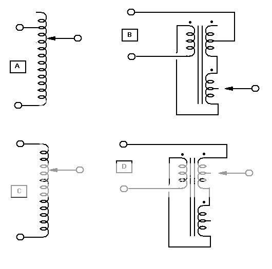
Fig.A is a variac configured for boost, fig.C is a variac configured for cut. Fig.B is the equaivalent to A, fig.D is the equivalent to fig.C
Using a 6.3V transformer configured like fig.D will cause the voltage to be stepped down about 5%, just what you wanted.
The correct way to do it would be with a 6.3V transformer connected as an autotransformer. The amperage of the secondary must be equal to the amperage of the primary of your transformer.
Fig.A is a variac configured for boost, fig.C is a variac configured for cut. Fig.B is the equaivalent to A, fig.D is the equivalent to fig.C
Using a 6.3V transformer configured like fig.D will cause the voltage to be stepped down about 5%, just what you wanted.
rtill said:I just ran it the way it is...works fine. However, I have seen this done on several amps....I am surprise to see people post that "it doesn't work this way"
A power resistor to lower voltage from transformer/supply is no good.
Because the drop will change with the current drawn.
Say you have a 2 Volt drop at idle.
At max output you may have 20V or more drop across resistor.
Which gives the power supply voltage will be only +-20 Volt ......
A slightly better way is to use some power rectifier diodes.
Across each diode will be like 0.5 to 1.2 Volt maybe. Depending on current level.
This will stay more constant even at max current drawn.
------
But,
for Power Amplifier a difference of +-40 or +-42 Volt is nothing.
Because if the voltage is+-42 at idle, it may well be only +-36 Volt at full power output.
Anyway ...
lineup said:
A slightly better way is to use some power rectifier diodes.
Across each diode will be like 0.5 to 1.2 Volt maybe. Depending on current level.
This will stay more constant even at max current drawn.
------
...
that's very interesting! I appreciate the response, learn something new everyday I guess.
if.....
music comes out of it it doesnt mean that is working properly ....
then again line up approach with the diodes is a start .....
but lets see it in another way
to my understanding there is no amplifier that is designed for operating with 40+40 volts that will not stand 42+42 ..... unless the amp is designed for 35+35 originally
post a schematic ...... be more specific about the application
rtill said:
that's very interesting! I appreciate the response, learn something new everyday I guess.
music comes out of it it doesnt mean that is working properly ....
then again line up approach with the diodes is a start .....
but lets see it in another way
to my understanding there is no amplifier that is designed for operating with 40+40 volts that will not stand 42+42 ..... unless the amp is designed for 35+35 originally
post a schematic ...... be more specific about the application
There is the LM3886 which has a rail limit of around +/- 40VDC, but I have breached that with no issues.
May eventually burn out the chip, or cause other reliability problems...
May eventually burn out the chip, or cause other reliability problems...
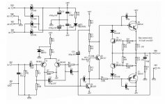
here's the schematic....supposedly 200 watts, is this possible?
I have had a few issues since 1st posting. The tip142 wasn't secured properly, got too hot and exploded. Replaced it and now it blows fuses once it is turned on. What would cause this? I would imagine something else in the circuit is blown to now cause the fuses to blow.
I have had a few issues since 1st posting. The tip142 wasn't secured properly, got too hot and exploded. Replaced it and now it blows fuses once it is turned on. What would cause this? I would imagine something else in the circuit is blown to now cause the fuses to blow.
Attachments
your amplifier as is
looks like a very insecure thing
42 volts for this amp is not a problem but working with loads lower of 8 ohms is absolutelly oyt of the question .....
for shure not only tip 142 was blown from not being properly attached to the heat sink ...somehing else is gone too .....
aslo
there is a big issue about tip 142-147 and cousins bdv66-67 bdw 83-84 c...to work in an audio amplifier they need to be the same make and from the same production line ...IE you cannot use tip 142 from philips and tip 147 from ST ....usually it doesnt work
also this amplifier will produce about 60W at 8 ohms load but operating in lower load like 4 ohm will be stressing outputs like hell
you have to be very carefull with idle setting a bit too much idle will bring the smoke in to your amp
amplifiers working with these outputs may be simple but never stable upgrade option will be to use very nice metal can transistors from on semi MJ15015-16 diferent case but very reliable
amplifier needs a quiet big heatsink and vbe multiplier transistor 6, BC547 needs to be in very good thermal contact with the heatsink to monitor temperature and reduce idle respectivelly ....
amplifier like that if not made properly will oscilate like hell ...meaning that the usual methods like zobel with inductor decouplers bypassed here and there have to be installed .....
figoures of 200w as mentioned somewhere above is absoltuley out of any question .....you will never get them with an amp like that
regards sakis
Since the BC547/BS557 is only 'good' for Vce of 50V and depending on how the TIP142 blew up, there is a pretty good chance that more defective parts are involved and responsible for the (still) malfunction of your amp. The TIP142/TIP147 will withstand a Vce of 100V therefore no harm for them is expected with rail voltages of ±42V though.
A good point to start is the bias transistor T6. If he is blown and makes an open circuit both power stage transistors (T7 & T8) will conduct and draw a lot of current from the rails. Be in luck if they're not blown again and the rail fuse(s) always blow first. The current limiter T4 and T5 may be damaged too in the first place. Once they are blown, either open or short circuit, they will either never protect anymore or protect all the time.
Furthermore look for burned and/or discolored resistors and check for correct value(s) as stated in the schematic.
Good luck though.
Re: your amplifier as is
the .47 ohm resistors test ok. In the past when I've had a transistor blow, the power resistor follows, this is not the case this time.
in your experience what else could have gone?
sakis said:
for shure not only tip 142 was blown from not being properly attached to the heat sink ...somehing else is gone too .....
the .47 ohm resistors test ok. In the past when I've had a transistor blow, the power resistor follows, this is not the case this time.
in your experience what else could have gone?
Corax, your post I think answered my question, thanks. We must have been responding at the same time!😀
Yip - just with a 4 minutes delay (according to the time attached to each post). ;-)
I hope it helped at least a little bit. The finding/checking procedure for defective components is now up to you.
You may report your progress and what you'll be able to figure out.
Have fun.
I hope it helped at least a little bit. The finding/checking procedure for defective components is now up to you.
You may report your progress and what you'll be able to figure out.
Have fun.
- Status
- Not open for further replies.
- Home
- Amplifiers
- Solid State
- reducing voltage