OUCH!
Mine looks like :
Potter & Brumfield - KHU-17D11-24VDC - Relay, DC. 4PDT 3Amp 24VDC.
Thanks for the source. i did not know of them.
Mine looks like :
Potter & Brumfield - KHU-17D11-24VDC - Relay, DC. 4PDT 3Amp 24VDC.
Thanks for the source. i did not know of them.
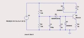
D3 will keep Q1 from turning on. Or limit it to a very low leakage current value and burn it up with too many milliwatts.
2n2222 make a *****y relay driver anyway. 500 mw is not much. Try $.35 tip31c or something. Reason for the c suffix, they cost $.01 than the 40 Vceo versions and can be useful for up to 80 v supplies later.
2n2222 make a *****y relay driver anyway. 500 mw is not much. Try $.35 tip31c or something. Reason for the c suffix, they cost $.01 than the 40 Vceo versions and can be useful for up to 80 v supplies later.
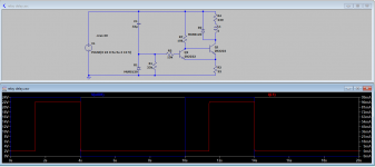
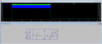
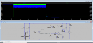
Yea, my simulation seems to be greatly in error. For one thing, I was not saturating the transistor. How Spice missed this I do not know.
Choice of parts were what was in the bin. I did just find a TIP-120, but the 2222 should be fine. I only pull 35mA through the relay. Thought I had some '30 and 32's in the bin but they were all LN79xx somethings.
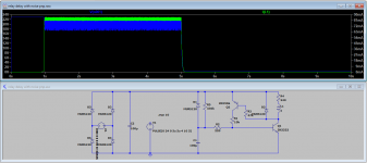
Power supply is super clean. If my change in base current ( to 4mA) does not get it working, I'll give that one a try. Unfortunately Ib requires a much larger main cap.
It has been about 20 years since I built anything. Not thinking on my part. I guess I was a manager too long.😀
Choice of parts were what was in the bin. I did just find a TIP-120, but the 2222 should be fine. I only pull 35mA through the relay. Thought I had some '30 and 32's in the bin but they were all LN79xx somethings.
Power supply is super clean. If my change in base current ( to 4mA) does not get it working, I'll give that one a try. Unfortunately Ib requires a much larger main cap.
It has been about 20 years since I built anything. Not thinking on my part. I guess I was a manager too long.😀
Relay is a 24V. Picks at about 17. A lot more relays are available in 12 or 5V though much cheaper if I have to buy one.
Sim suggests I need to look at the rise time and output impedance for the SNPS feeding it to limit the spike on D1.
Built a temporary circuit while I wait for better parts to build as above. I used a little 12V delay on relay board I had off Amazon to control my 24V relay. Just stuck a LM7812 in front of it. It should drop as soon as the 24V supply drops.
Here is my catch 22.
I think I have power up licked, ( 2 seconds) but power down is still a problem. I added a 4700u cap to the crossover board side of the power supply, isolating it from where I tap my control circuit. (diode for isolation, resister to limit inrush). The hope was one: filter the SMPS output which it does fine, and second to hold the supply up long enough for the relay to drop. But it is still way too slow to drop the relay. Now, I could go to a mains sequencer to hold the crossover and pre up longer than the power amp and the sub amp to power down, but that does not help with a power fault.
Looking for a way to make the relay drop faster. Much faster. Am I going to have to resort to opto-couplers in the signal path for increased resistance rather than grounding? Distortion to the SUB is not an issue, but to the mains it is.
Wish I had a storage scope so I could see the timing for real. Just an old Tek.
Crossover supply drops in less than 50ms, so way faster than the relay.
The power off if mains fault is what is defeating me so far.
The power off if mains fault is what is defeating me so far.
I built a sequencer for my triamp setup way way back (decades ago) and used a 555, counter chip, and to provide instant off, a mid400 chip which is an opto-coupler driven by the mains with a logic output. I looked it up and it still made.
Had a thought. I could bypass the on-board regulators and artificial ground in the crossovers, replace it with an external +/- soft start tracking supply. That would eliminate both the ground stabilization as well as offset on coupling caps.
Maybe get the problem reduced to a tic, not a KaWhump Then power on sequence on and off woudl be silent, but power fault would not damage anything.
Yea, I could leave things on, but my Asgard DAC/pre pulls 15W quiescent and the crossover darn near that.
Maybe get the problem reduced to a tic, not a KaWhump Then power on sequence on and off woudl be silent, but power fault would not damage anything.
Yea, I could leave things on, but my Asgard DAC/pre pulls 15W quiescent and the crossover darn near that.
Making it drop out fast(er) also makes it sensitive to PS noise. The best plan is a separate rectifier for a supply that falls out faster than the audio circuit. This could be a diode between the PS and the large storage cap, and run the relay from before the diode so that the relay power is gone while the storage cap is still ~up.
Another possibility is audio supply regulation that hides the PS drop-out until the relay has dropped out. The relay is driven by the regulator drop so that it closes after the audio PS is up and open before the audio PS fails.
Another possibility is audio supply regulation that hides the PS drop-out until the relay has dropped out. The relay is driven by the regulator drop so that it closes after the audio PS is up and open before the audio PS fails.
Yup, the first is what I did. Diode to a 4700uf through a 4 Ohm resister. But the audio regulators, being set by a voltage divider not a zener, the drop of a couple volts is enough to be seen as a pulse and that happens before the 3ms it takes for the relay to drop.
Idea two would only work on a normal shut down. It would not work on a power fault. Power fault is what has me stumped. Otherwise, just a mains sequencer would mask everything.
Looking at putting an opto-coupler in-line. NLS-32SR2 or something. I should be able to get an LED to turn off faster than a relay. Combine that with a split supply on the crossovers. I thought I was doing a simple upgrade. Turned out to be full of issues.
Darn SMT boards. I don't look forward to doing changes on them. I guess the bright side is they are only 2 layers. OK, coffee is ready. Time to ponder a bit more.
There are SS relays that provide delay and instant off to prevent turn on and turn off thump. The SSRs carry high currents and add no measurable distortion and will not wear out like mechanical contacts. I use them and they work very well and offer DC protection to boot.
For small signal line-level, a small high quality signal relay with gold/iridium contacts works well enough. You will still need a delay and instant off circuit to control it.
For small signal line-level, a small high quality signal relay with gold/iridium contacts works well enough. You will still need a delay and instant off circuit to control it.
Typical Triac SRs for power switching are a disaster for audio as they produce an asymmetrical wave and will cause a transformer to buzz like all get out. Toroid's the worst, but can buzz an E-core too. I learned this the hard way. If you know of specific devices that are well behaved, please let me know. I have been told there are MOSFET SSRs but very expensive.
The signal relays I am using are the very expensive old data relays, current cost well over $100. The usual CMOS audio switches are not very low distortion, neither are the gain control chips. About the only in-line device I can come up with is the opto coupler that does not add measurable distortion and that is only when hard on.
Again, it is the power fault scenario that has me stumped. Plain old mains sequencing can mask the normal conditions. It is that instant off that I can't solve. Instant to me and you is one thing, quite a different thing to the crossover power supply virtual ground. Reducing the core problem seems like my only solution. No way to mask it.
The good news is I dragged out my measurement suite this morning and tweaked my tone controls and sub level. Got things balanced out quite well. New DAC/pre, crossover and amp do sound quite nice.
Back to back ultra low RDSon MOSFETs (80A, 150v, 10.5mOhm) can handle high current (80A) and add no distortion are about $3ea. Look in the GB forum - there are several designs there that are not expensive to DIY.
Here is a prototype unit designed by Jhofland. It’s the second generation, and if there is interest we could do a GB.
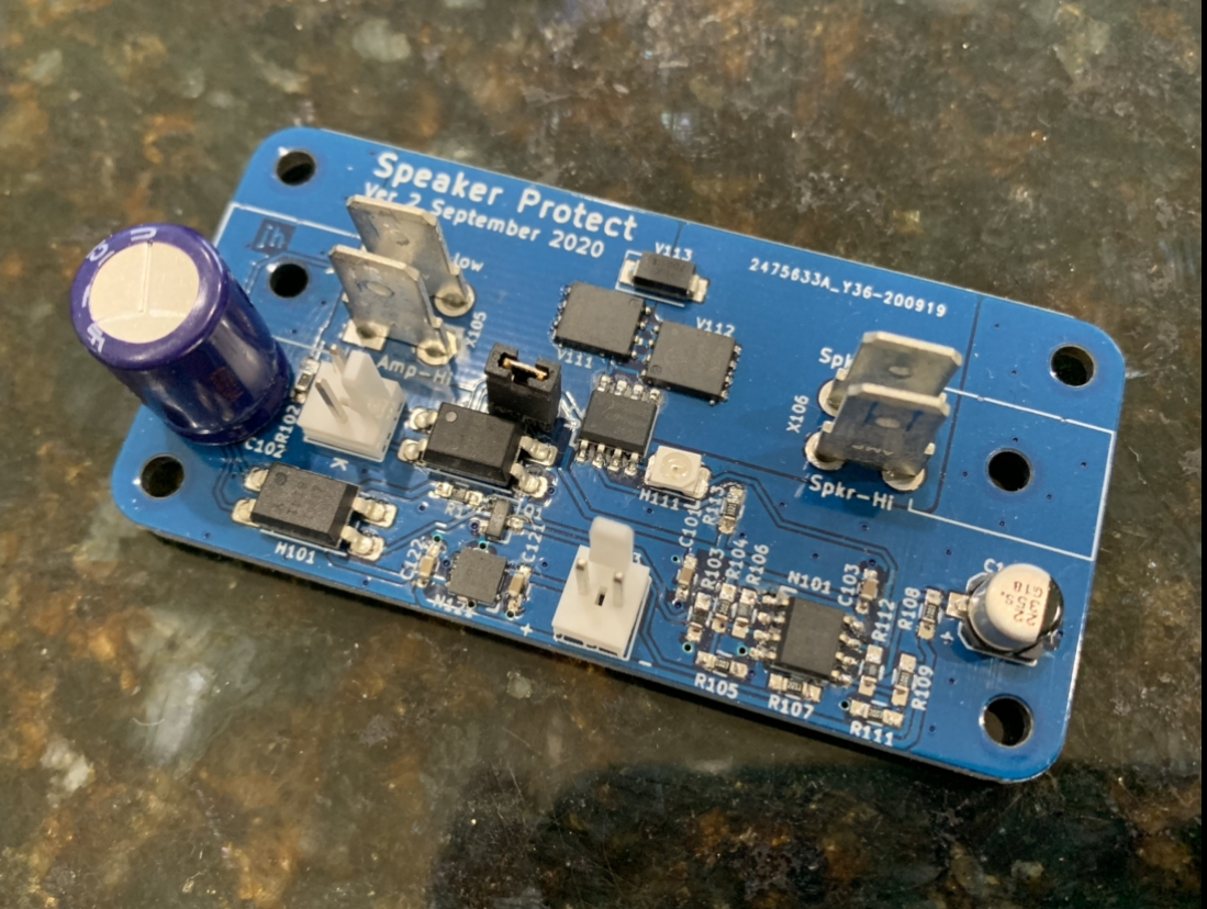
Here is a prototype unit designed by Jhofland. It’s the second generation, and if there is interest we could do a GB.
Last edited:
Turn-off thump is typically caused by asymmetrical decay of the power supply rails and at some point in that process the closed loop function of the amplifier collapses and the output tends to pull to one of the two rail voltages. The two ways of avoiding the thump in the connected speaker is to either carefully control the decay process to be slow and symmetrical or to disconnect the speaker from the amp output before the thump occurs. The former is very difficult to do and often not worth the the complexity to do so. The latter, disconnect of the speaker, is relatively straight forward if you have a speaker protection in place, such as the aforementioned SSR, and a means to open the SSR when loss of power is sensed. A relatively straight forward means to do that is a simple rectifier based supply in parallel with the main supply on the same transformer secondary and a relatively low capacitance so it bleeds down fast compared to the main supply. Use this supply to give an enabling current to the SSR so it shuts off when the auxiliary supply goes down well before the main supply.
Very interesting concept. Several things I have not seen before. I can see how the concept could make a superior mains SSR.
I can see how the above application is pretty nifty for it's intent. Mechanical relays on the speaker terminals have been the bane of high end forever. Might even think about a couple for my sub amps as they have have no output disconnect and do a small thump on their own in normal operation. My new main amp (Parasound 2125) does not thump itself if the plug is pulled but will pass the crossover Kawhump before the relay has dropped.
Coffee time.
My problem is different from what this idea solves. It would have to be faster than not the amp power supply, but the crossover power supply. I'll take the idea and think if it would be an alternative to the opto-coupler for low voltage, low current with different devices.
Yes, it is the collapse of the power single rail with virtual ground on the crossover boards that is the root problem. By definition, I have a 9V DC bias on the coupling caps. This is the source of the KAWHUMP, rather than a little thump. It happens in less than a ms so is faster than any mechanical relay, like the one on the power amp, can physically drop. It passes as a valid signal while everything is still up.
Slightly easier may be to go back to a linear supply with massive caps so it bleeds down slowly. I might be able to test this without modifying the boards, but eliminating the standing bias looks like a good start. If I get it to a manageable size then power fault is only annoying and the sequencer ( should be here Tuesday) will take care of normal operations.
- Home
- Amplifiers
- Solid State
- Reducing thump