Artnyos:
>The circuit is complicated enough as it is now; and more parts complicate stability, lengthen signal paths (and complicate ground current return paths which are critical) and make PCB layout more difficult.<
You are right, I do tend to ignore issues of complexity and difficulty when designing circuits and pcb layouts.
But a circuit wouldn't be fun if it didn't present a worthy challenge ;-).
regards, jonathan carr
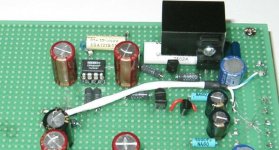
PCBs
I noticed..... PCB layout is a little more complicated when the parts are actually on the board.
I got tied of 3Dcircuits when doing mods on circuit developement on telcom boards using SMT parts. I have done a few under a microscope. I try to do point to point with the parts in one plane. Much easier to measure, fix, or modify. But as they say, "Whatever floats your boat."
Art
I do tend to ignore issues of complexity and difficulty when designing circuits and pcb layouts.
I noticed..... PCB layout is a little more complicated when the parts are actually on the board.
I got tied of 3Dcircuits when doing mods on circuit developement on telcom boards using SMT parts. I have done a few under a microscope. I try to do point to point with the parts in one plane. Much easier to measure, fix, or modify. But as they say, "Whatever floats your boat."
Art
Push pull
ALW Andy: Looking at the schematic that you posted on the first page of this thread, how about doing a version of your regulator with a push-pull output?The schematic I'm working with is closer to that at the top of p6.
I don't feel PP offers any great benefits, and brings with it extra complication. For the power levels we're talking about for preamps, the reg. o/p can always be pre-loaded with a resistive load, in order to provide some current sinking capability.
I've used this scheme in a number of apps.
A.


This is probably the most informative and important thread on the whole of diyaudio.com. Thanks for so much great information.
My question is what to do about 5V and 3.3V supplies. If I need e.g. 5.5V for the analog side of a DAC, I can't use any of these designs that include LM329, because that is a 6.9V reference. If I feed the output of a Sulzer regulator into a regulator such as LT1962, will the LT1962 simply add back in a bunch of noise? How much noise do standard regulators generate internally?
I realize that a 5V supply filter was discussed in the very first page of this thread, but it doesn't answer the question of how to apply the Sulzer or similar regulator to a logic-level supply.
The 5V logic supply
Here's my solution...
Jung reg, THS4271 op-amp (3nV/rt Hz, 1000V/us, 1.4GHz GBW!), TL431 set to it's reference voltage of 2.5V.
THS4222 could be promising for 3.3V, but is noisier @ 13nV/rt Hz.
A.
Here's my solution...
Jung reg, THS4271 op-amp (3nV/rt Hz, 1000V/us, 1.4GHz GBW!), TL431 set to it's reference voltage of 2.5V.
THS4222 could be promising for 3.3V, but is noisier @ 13nV/rt Hz.
A.
Has someone tried made a sulzer type rugulator with high speed comparator (like ad8561) ?
I guess they much faster than opamps, but have lower gain and i do not know about noise voltage.
Have a nice day,
borisov57
I guess they much faster than opamps, but have lower gain and i do not know about noise voltage.
Have a nice day,
borisov57
Re: Sulzer type regulator
how much current can be constantly drawn from one of these supplies??
Also i cant find those transistors in my area, will any low noise NPN/PNP pair work?
artnyos said:
how much current can be constantly drawn from one of these supplies??
Also i cant find those transistors in my area, will any low noise NPN/PNP pair work?
Voltage regulators ... they always come up in every project! Here's the thing:
1) Building yet another DAC
2) Some logic is 3.3V
3) Some logic is 5V
4) The analog side of the DAC needs ??
5) The clock also needs 9V
So I'm in the position where I need 3.3V, 5V, and 9V regulators, where the 9V needs to be quiet out to the clock speed of ... 24.576MHz. I like these Sulzer and Jung regulators designs, but I like the Sulzer better because it runs from the bulk supply, not the regulated supply. This allows me to run all the opamps from +15V bulk, instead of trying to find a good opamp that can run from a 3.3V single supply.
For the 9V supply, I can easily use the bog standard Sulzer with LM329 reference. To get the bandwidth I want I could go with AD797, it has serious specs. The problem I see in the Sulzer schematic is the huge AC feedback capacitor. Why 4.7uF? This rolls off the feedback at a very low frequency. The 797 has plenty of open-loop gain left to burn at 1MHz, and the closed-loop gain of the regulator would be only 2.3, so why not use 100pF for the AC feedback? Am I looking at the wrong impedance spec on the capacitors?
For the 3.3V and 5V regulators I believe I will use the solution ALW posted above. Thanks for the tip on the THS4271.
-jwb
Heh, I'm waiting for the first guy to jump in and say "jwb -- you are a huge moron!". I just don't understand electricity before I've had my first cup of coffee. I should remember that before I start typing into this little box.
I shall try to redeem myself. C3 and R3 form a <em>high-pass</em> filter, not a low-pass. They ensure DC stability below 11HZ The op-amp is internally compensated, we don't need to worry about HF stability.
I shall try to redeem myself. C3 and R3 form a <em>high-pass</em> filter, not a low-pass. They ensure DC stability below 11HZ The op-amp is internally compensated, we don't need to worry about HF stability.
OK, If I have a very, very clean +-12 volt DC supply and I need to pull it down to 8.5 to 8.9 volts DC should I use the 1086 and 1186 as I already have these or is there a Zener that will set the output in the range stated above. Thanks
since there is interest in these things from time to time, here is YALNR.
Courtesy of Maxim (so you know who's chips it uses 🙂 ) from latest EDN, which, BTW, is a pretty good trade rag.
http://a330.g.akamai.net/7/330/2540/20050614152946/www.edn.com/contents/images/62305di.pdf
(last two pages)
Courtesy of Maxim (so you know who's chips it uses 🙂 ) from latest EDN, which, BTW, is a pretty good trade rag.
http://a330.g.akamai.net/7/330/2540/20050614152946/www.edn.com/contents/images/62305di.pdf
(last two pages)
Pretty ordinary - appears dominated by the op amp noise which is > 4.5nV/sqrt Hz.
Hi jwb,
have you considered a nested FB loop using 2 op amps to find some gain at 25MHz. Only the first needs to be ultra low noise.
If it's commercial I may let you use my integrator nesting concept which has been patented by others but I have established prior art.
Is DC drift of the reference a concern?
Greg
- Status
- Not open for further replies.
- Home
- Amplifiers
- Solid State
- Reducing noise in voltage regulators