Please add what I've said earlier that the PT sized for 200mA most probably cannot hold a quad of power tubes.
Hello all,
The bias resistors are a 1R in series with a 620R with a 25uF across them. This resistor combination is per pair of output tubes. This is what the designer had specified for Tung Sol KT66's. If I was to try separate cathode resistors for each tube, would I half the value of the 620R? Or something completely different? Also would the bypass caps have to change as well?
As for the fuse, it is built into the IEC inlet and is before the switch.
Alan4411, you are correct, the B+ for the output tubes comes from before the choke. After the choke is for the screen grids for the KT66's, the EF86, and the inverter. Would this choke be sufficient with this in mind? Also, as previously mentioned I temporarily replaced the choke with a 600R resistor and that had no effect on the buzz.
I will try the steps mentioned and report back:
1K 12AT7 grid stopper. disconnecting the PT outputs and test which load is making the buzz. measure voltage at pin 8 of the power tubes.
Please let me know if there's any other things I should try or change.
Thanks guys
I did that previously by replacing with a 600R resistor and that had no effect on the buzz. I did forget to edit the tube designation, They are in fact Tung Sol KT66's.You could replace it temporarily with an appropriate power resistor and see if the buzz goes away.
The bias resistors are a 1R in series with a 620R with a 25uF across them. This resistor combination is per pair of output tubes. This is what the designer had specified for Tung Sol KT66's. If I was to try separate cathode resistors for each tube, would I half the value of the 620R? Or something completely different? Also would the bypass caps have to change as well?
As for the fuse, it is built into the IEC inlet and is before the switch.
Alan4411, you are correct, the B+ for the output tubes comes from before the choke. After the choke is for the screen grids for the KT66's, the EF86, and the inverter. Would this choke be sufficient with this in mind? Also, as previously mentioned I temporarily replaced the choke with a 600R resistor and that had no effect on the buzz.
I will try the steps mentioned and report back:
1K 12AT7 grid stopper. disconnecting the PT outputs and test which load is making the buzz. measure voltage at pin 8 of the power tubes.
Please let me know if there's any other things I should try or change.
Thanks guys
But I think the design intent is B+ for the output valves comes from the point before the choke, so the choke only carries KTxx Screen Grid, EF86 and phase splitter current. Hence the 30H / 40mA designation?
Good point.
1 ohm over 620 ohm is less than 2%. With variance in tubes don't see the point. I'd chuck it.
For separate cathode resistors you need to double the resistance since the current is half...assuming you want the same bias voltage that is...
Cap can stay the same, assuming it was appropriately sized to begin with.
For separate cathode resistors you need to double the resistance since the current is half...assuming you want the same bias voltage that is...
Cap can stay the same, assuming it was appropriately sized to begin with.
In that case measure B+ 1 and output anode volts (pin 3) and SG volts (pin 4) we can work out the current and dissipation from there...
Thanks guys,
I’ll take some measurements this weekend and order some resistors for separate bias resistors and let you know what I find.
What is the point of 1R resistors is series in the buss circuit? I’ve seen it on some other prints as well.
Thanks
I’ll take some measurements this weekend and order some resistors for separate bias resistors and let you know what I find.
What is the point of 1R resistors is series in the buss circuit? I’ve seen it on some other prints as well.
Thanks
1R resistors are for measuring the cathodes current. 1mV across them is 1mA. Anything over 25mA per tube is bad news for your PT.
during finding source of buzz need oscop to see power + line.why we cant see these kind of pictures here ?
I do have a scope. I will post pictures of the scope at each of the filter stages this weekend.
Thanks
Thanks
In my experience Hammonds tend to buzz more than the competition. They are outsourcing some of the products from China so it doesnt surprise me.
I had Edcor wind me some transformers to replace my GM70amp PT's that were buzzing. remove the load and tell us if the buzzing attenuates.
I had Edcor wind me some transformers to replace my GM70amp PT's that were buzzing. remove the load and tell us if the buzzing attenuates.
My Hammond 278CX both buzz. The bell ends vibrate. I live with it on that amp, and use toroidal or SMPS for my new builds.
Yes they do buzz. I got a pair to use on my GM70 amps to get a bit more voltage and less transformer heating. To quiet them down I first took the end bells off laid them flat and filled them with 6-8 mm of silicone to deaden their vibration. Then I sealed the end bells all around with flexible gasket, heated the transformers and poured in transformer varnish, let them cool and poured out the excess (twice) then I mounted them on rubber grommets. No more buzz. But it was a bit of work. I think Hammond needs to cut back on the design and redo them maybe for 400 mA rating.
The exact order on this bus is crucial. The new diagram in post 15 does not add any useful details on this as it still uses the 'ground' symbol.Diyengineer said:All P.S. grounds including the HV C.T. and filament C.T. are bussed together
Thank you DF96,
Would you be able to give me a quick explanation with details of how you might ground this amplifier? I followed a scheme that I have used successfully in other amps, but maybe it doesn’t work the best for this design.
Thank you again
Would you be able to give me a quick explanation with details of how you might ground this amplifier? I followed a scheme that I have used successfully in other amps, but maybe it doesn’t work the best for this design.
Thank you again
Check how much voltage is across the 620 Ohm resistors. For example, 31 Volts would be 50mA per pair of KT66 tubes. That would be 100mA for the four tubes. Perhaps you have much more bias voltage and current than that.
The 273BX might not hum with a choke input supply (and a proper choke). Of course the B+ Voltage will be quite a bit less that way. For a 700V CT transformer, you might get 315V B+. And you will need another stage of RC coupling to get the ripple reduced. Choke input supplies do Not have large transient rectifier currents. The transformer will run cooler. The 273BX should be able to deliver 200mA to a choke input supply, and should be able to run cool doing that; it just might not have mechanical hum that way. Depending on how much current there is with 315V B+, you might have to re-adjust the self bias resistors to get the KT66 current and a good operating point.
Again, I recommend individual self bias resistors and bypass caps for each KT66. with only 315V B+, the individual self bias resistors might have to be nearer to 500 Ohms than 2 x 620 Ohms / 1240 Ohms to get enough current.
Or you could use individually adjustable fixed bias for each KT66. With fixed bias, you have to build a negative bias supply, but then you can use individuals 1 Ohm sense resistors to ground from each cathode. The low voltage across the 1 Ohm resistor (and no other resistor in the cathode) will allow you to effectively get back some of the B+ you lost with a choke input supply. Effective B+ is from the cathode to the plate, not from ground to plate.
But with a cap input supply of 200uF and solid state diodes, it just might hum. The more current there is in the load, the more likely the transformer will hum. Cap input supplies Do have large transient rectifier currents. The transformer will run hotter.
100mA and 220uF will give about 600mV peak to peak ripple (to the output transformer center tap), which is about 200mVrms. That seems a little to large for powering the center tap of the output transformer. Tube mismatch will cause hum, even if the volume control is turned down.
It seems you have lots of investigation to decide what to do with what you have, and to decide if a few more parts, or different parts may be needed.
Last edited:
Diyengineer,
I was re-editing my post when you posted # 36.
You might want to re-read my post # 35.
I was re-editing my post when you posted # 36.
You might want to re-read my post # 35.
Hello all,
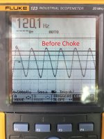
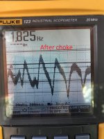
Here are my findings and a couple pics from my scope. (the dark horizontal lines are dead pixels, I need a new one).
All of these measurements are with the circuit as is in circuit #15 after a 5 min warmup and a 4R dummy load on the 4R tap.
HV PT: 717VAC/ 358.7VAC ref to ground each side.
After Diodes: 446.2VDC
Before Choke: 443.8
After Choke: 436.8
Pin 3 all power tubes: 442.0
Pin 4 all power tubes: 436.0
Pin 8 all power tubes: 44.2
Bias circuit per pair of KT66 tubes:
across 620R:
1)44.3V
2)44.2V
across 1R:
1)70.7mV
2)70.4mV
So as Alan4411 mentioned,
I disconnected the HV outputs from the PT and the trans went silent then I reconnected.
Disconnected the EF 86 plate, buzz was still there.
Disconnected the 12AT7 plates, buzz was still there.
Disconnected the output trans, buzz was still there.
Disconnected choke output side, buzz went very quiet then reconnected.
Disconnected individual screen grid wires leaving rest of filters and circuit intact, buzz was very quiet.
Would this mean the tubes are biased incorrectly? I do like the idea of separate cathode resistors. Please let me know if there is another measurements to take or circuit changes to make.
Thanks for all the help guys!
Attachments
Interesting but confusing ehy?
So the 4 x KT66s are drawing 140mA in total. Well in the capability of your 200mA transformer.
Thought you might have seen a little more DC volts at B+, but no concern.
Basically you have 400v DC (440 HT - 44 Bias = 400) so again each KT66 is only dissipating 14 Watts (400 x 35mA ) an easy life for them.
So far so good, now if you disconnect the output 'from' the choke the transformer goes quieter? I am confused now... There is only 12mA through the choke (7 volts drop over 600 ohms) ...and you have 390 volts on the screen grids ...and that second trace?
Ok another question whilst I think, on the diagram after the choke there is another set of filters, 47uF - 10k - 47uf - 22k - 47uF do you use these to go to the 12AT7 and EF86 respectively or what do they do?
I think they are biased correctly for the application and available power ratings you have. I think individual 1.2k ohm 5 or 7 Watters would be ok. (Still only 40mA ish per valve and 16 Watts dissipation.)
Only 12mA through the choke?
That will not make a working/good choke buzz.
It sounds to me that the B+ for the output tubes are actually also connected to the choke output.
Power down the amp.
Discharge All filter caps.
Measure the DCR of the choke, DCRc.
Power the amp on.
Measure the DC volts across the choke, Vc
Vc/DCRc = mA through the choke, Ic.
Check that it is only 12mA, not 140mA or more.
(Sometimes amplifier wiring and schematic do not agree).
Even if you do not use individual self bias resistors and bypass caps, at least you ought to do this:
Use two 1 Ohm resistors, one from each cathode to the 620 Ohm resistor of one pair of KT66s. Do the same with two more 1 Ohm resistors, and the other 620 Ohm resistor and tube pair. Then with your DMM you can measure the individual cathode currents.
But that means you have to measure across each 1 Ohm resistor, not from the 1 Ohm resistors to ground.
DC current balance in push pull transformers is very important, because they are Not air-gapped laminations (like single ended transformers which are air gapped).
If you do use individual 1200 Ohm resistors, you can eliminate all the 1 Ohm resistors, and just measure the volts across the 1200 Ohm resistors. Be sure to increase the capacitance of the individual bypass capacitors (they all have their own changing currents, not the balanced currents of the original shared bias resistors).
I would use at least 330uF, and for safety use 63V caps (If one tube somehow self biases to say 55V, it will not blow up a 50V rated cap).
If the currents do not match, you ought to get matched tubes.
Last edited:
- Status
- Not open for further replies.
- Home
- Amplifiers
- Tubes / Valves
- Reducing gain in a monoblock