For the problem of the inductor has a "hiss, hiss, hiss" or "ji ji ji" sound in the normal operation of the class D circuit. this is has big effect of the sound quality . here is my sharing of analyse and solution .
Cause Analysis:
1. The winding of the inductor enameled wire is loose. (The coil is impregnated need dip in varnish to avoid the coil loose )
2. PWM dimmable output power supply, inductor noise. (PWM produces audio resonance and EMI interference signals during dimming. The ripple current increases with power changes. (Use magnetic powder core inductors/one-piece inductors instead, varnish strengthens the inductor coil and increases the output filter capacitor capacity. Can be reduced noise.)
3. The inductor exceeds the maximum current and the margin is insufficient, resulting in the decrease of the inductance electrical characteristics and the deterioration of the magnetostriction. (we need choose a large-size inductor to ensure that the peak current of the inductor in the circuit is 1.3 times greater than the inductor's rated current.)
4. The circuit ripple current is too large, the electrical characteristics of the inductor are reduced, and the irregular vibration of the inductor coil is aggravated. (Varnish is impregnated to strengthen the inductance coil. Increase the inductance in the BUCK circuit, and increase the filter capacitor in the boost circuit. Reduce the electrolytic ESR or use ceramic capacitors.)
5. The switching frequency is too low, within the audible range of human ears (20-20K). (Where Varnish reinforces the coil, or use a magnetic powder core with low hysteresis expansion, or apply an integrated inductor. Adjust the power switching frequency on the circuit. Avoid the audible range of the human ear.)
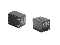
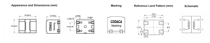
There is an axample of the sound of the power amplifier channel is poor. customer's project tested the inductance of 3 defective products, and the inductance of the 3 channel inductance was 22uh, 2.8uh, and 4.7uh. customer usesCODACA digital power inductor CSD1013B-100M, which is applied to the output of the digital power amplifier.
Cause Analysis:
Because the customer's inductance is tested on the PCB board, it is possible that the chip, other components and connections will affect the accuracy of the test. Therefore, the two inductors are removed separately and tested separately to be accurate.
Defective product 1: 4.7uh measured value 9.7uh (10uh is normal)
Defective product 2: 2.8uh measured value 0.84uh, (10uh becomes smaller)
Open the measured 0.84uh inductor and observe the inner coil of the inductor through a microscope. It is found that the varnish water between the coils is black. It is suspected that the flat enameled wire is damaged during the IQC or the production process. In the case of the customer's high current test, the layer is short-circuited. , Resulting in smaller inductance.
Solution :using varnish to strengthen the coil and test frequency is increased to 100K/1V to prevent the defective .
For learn CSD1013 design click https://codaca.com/en/product/230.html
Cause Analysis:
1. The winding of the inductor enameled wire is loose. (The coil is impregnated need dip in varnish to avoid the coil loose )
2. PWM dimmable output power supply, inductor noise. (PWM produces audio resonance and EMI interference signals during dimming. The ripple current increases with power changes. (Use magnetic powder core inductors/one-piece inductors instead, varnish strengthens the inductor coil and increases the output filter capacitor capacity. Can be reduced noise.)
3. The inductor exceeds the maximum current and the margin is insufficient, resulting in the decrease of the inductance electrical characteristics and the deterioration of the magnetostriction. (we need choose a large-size inductor to ensure that the peak current of the inductor in the circuit is 1.3 times greater than the inductor's rated current.)
4. The circuit ripple current is too large, the electrical characteristics of the inductor are reduced, and the irregular vibration of the inductor coil is aggravated. (Varnish is impregnated to strengthen the inductance coil. Increase the inductance in the BUCK circuit, and increase the filter capacitor in the boost circuit. Reduce the electrolytic ESR or use ceramic capacitors.)
5. The switching frequency is too low, within the audible range of human ears (20-20K). (Where Varnish reinforces the coil, or use a magnetic powder core with low hysteresis expansion, or apply an integrated inductor. Adjust the power switching frequency on the circuit. Avoid the audible range of the human ear.)
There is an axample of the sound of the power amplifier channel is poor. customer's project tested the inductance of 3 defective products, and the inductance of the 3 channel inductance was 22uh, 2.8uh, and 4.7uh. customer usesCODACA digital power inductor CSD1013B-100M, which is applied to the output of the digital power amplifier.
Cause Analysis:
Because the customer's inductance is tested on the PCB board, it is possible that the chip, other components and connections will affect the accuracy of the test. Therefore, the two inductors are removed separately and tested separately to be accurate.
Defective product 1: 4.7uh measured value 9.7uh (10uh is normal)
Defective product 2: 2.8uh measured value 0.84uh, (10uh becomes smaller)
Open the measured 0.84uh inductor and observe the inner coil of the inductor through a microscope. It is found that the varnish water between the coils is black. It is suspected that the flat enameled wire is damaged during the IQC or the production process. In the case of the customer's high current test, the layer is short-circuited. , Resulting in smaller inductance.
Solution :using varnish to strengthen the coil and test frequency is increased to 100K/1V to prevent the defective .
For learn CSD1013 design click https://codaca.com/en/product/230.html
Attachments
Abnormal sound:
The inductance has singing and music in the normal operation of the circuit. In the audio circuit, it appears as inductance and music, and in the power circuit, it appears as a system crash or circuit protection. The fault inductance is generally a two-in-one or three-in-one inductance, with multiple coil windings.
Cause Analysis:
1. There is a short circuit between the coils through the magnetic core, that is, a resistance value of 10-100K is generated. The inductance directly forms the output loop through the ground wire, which acts as a speaker, so there will be sound.
2. For the power supply, the two coil windings are indirectly short-circuited with each other, and the DC operating point of the two PIN pins of the IC changes, so the system will be protectively crashed. For digital power discharge, there is a serious heating phenomenon.