I can't see a single one of those pictures. :-( Have you by any chance hosted them on Google, rather than uploading directly into the forum?
Thanks for the responses, guys! There's some good ideas in there for sure.
Aqua Tarkus: A fair question, but no; I made certain I uploaded directly to the forum, if only to avoid annoying people down the road. Like most people it drives me nuts to return to a thread years (or even days) later only to find a bunch of zombie "Bloat-oh-pluck-it" links. I don't know about you guys, but it kinda' makes me feel like Clark Griswald when he arrived at Wally World. I wonder if this could be linked somehow to the recent server change. Heck I even made certain to back off somewhat from the maximum permitted size in deference to those still forced to use DSL (ooh). I hope this works itself out.
Shef: Thanks for the suggestion. I actually tried running the grain parallel, but it looked a bit weird to me (subjective, I know). It's not that apparent from the photos but the front caps are actually bookmatched when viewed from the top, and that effect is more apparent with the cap grain running fore-and aft. What's less apparent is that the pedestals and feet were assembled with all the end grains facing forward, and that gives a subtle but noticeable cascade effect when viewed in the right light.
BillWojo and Shef: You read my mind on the power supply! I had one of those "D'oh!" moments after the feet were attached and glued, realizing that I'd neglected to rout the slots for the wiring. That actually works out well for two reasons:
BillWojo: GP03 would be perfect; I think I'll use that instead - despite my reluctance to order "one more item". Relatively cheap to boot. Thanks again - but why didn't I think of that?.
20to20 and Brice: Thanks to both of you for the prodding and kind comments. For me the stance of those feet remind me somewhat of the Apollo LEM, but for some reason I keep wanting to call it the "Spider from Mars". 🙂 Those are the sort of things that keep me thinking outside of the box.
Aqua Tarkus: A fair question, but no; I made certain I uploaded directly to the forum, if only to avoid annoying people down the road. Like most people it drives me nuts to return to a thread years (or even days) later only to find a bunch of zombie "Bloat-oh-pluck-it" links. I don't know about you guys, but it kinda' makes me feel like Clark Griswald when he arrived at Wally World. I wonder if this could be linked somehow to the recent server change. Heck I even made certain to back off somewhat from the maximum permitted size in deference to those still forced to use DSL (ooh). I hope this works itself out.
Shef: Thanks for the suggestion. I actually tried running the grain parallel, but it looked a bit weird to me (subjective, I know). It's not that apparent from the photos but the front caps are actually bookmatched when viewed from the top, and that effect is more apparent with the cap grain running fore-and aft. What's less apparent is that the pedestals and feet were assembled with all the end grains facing forward, and that gives a subtle but noticeable cascade effect when viewed in the right light.
BillWojo and Shef: You read my mind on the power supply! I had one of those "D'oh!" moments after the feet were attached and glued, realizing that I'd neglected to rout the slots for the wiring. That actually works out well for two reasons:
- Those slots would have further weakened the most vulnerable part of the chassis (there's no aluminum there to give a "composite beam" effect).
- It allows me to use some sort of metal conduit as you described, which is an opportunity to shield the AC heater wiring from the DC supply.
BillWojo: GP03 would be perfect; I think I'll use that instead - despite my reluctance to order "one more item". Relatively cheap to boot. Thanks again - but why didn't I think of that?.
20to20 and Brice: Thanks to both of you for the prodding and kind comments. For me the stance of those feet remind me somewhat of the Apollo LEM, but for some reason I keep wanting to call it the "Spider from Mars". 🙂 Those are the sort of things that keep me thinking outside of the box.
Last edited:
+1Well, I'm not a fan of using anything combustion-able to build electronics on. My personal favorite material to build binding post or turret style circuits on is GP03 red fiberglass board. I purchase it from McMaster Carr along with brass screws and nuts to use as binding post. Makes a nice neat and attractive layout. Best to cut and drill with carbide, the glass fibers are abrasive.
The problem with wood is that it always retains some moisture and is conductive, typically in the region of some megaohms, which is enough to affect the behavior of the small-signal side of the amp. I've come across a few other instances of people building amps on a wooden substrate, and the results were never good.
Thanks for the confirmation; I'm completely sold on some sort of fiberglass composite.
I'll admit to having had a bit of a queasy feeling regarding my idea from the start. Looking through my old QST magazines (they're available on CD ROM) I get the impression that using wood as an insulating chassis material was merely an expedient suited to the time. Many of the materials we take for granted today were either beyond the reach of the common man (e.g. phenolics or ceramics), or simply didn't exist (fiberglass reinforced plastics). Wood wasn't ideal, but it was good enough.
BTW, were you able to get the photo issue sorted out?
Last edited:
Thanks for the confirmation; I'm completely sold.
I'll admit to having had a bit of a queasy feeling regarding my idea from the start.
I just checked a piece of "white hardwood," whatever that is. It's knot-free door casing I have laying here near the bench, and I grabbed my Fluke 77 that has a range of 32M on the resistance. I couldn't get any continuity reading of any megs. I put the probes hard into the wood without any gap between them until they touched and then tilted them away from each other. I couldn't even see between the probes as the meter read open circuit. No readable resistance. But, I wouldn't mount any resistor directly in close proximity. Use a couple of terminal strips to elevate the components that generate heat. I have a wood base on my DIY 6L6 and I used strips that way inside to get them up off the wood.
Last edited:
on my follow list. I'm a big fan of Poinz's aesthetic as well, and this looks like a fun and thorough build.
Thanks guys! It's good to see replies from so many long-time forum members. 6L6: I encourage you to finish yours no matter what stage it's in. To be truthful, the reason I started this thread was not only to get advice from other forum members, but to get off my bum and build - and hopefully inspire others to do likewise.
I myself was inspired to build again after taking in the Wauwatosa Tube Factory website by fellow forum member Sodacose. It may not be everyone's cup of tea, but his message is right in step with the point of this forum; to take the learning experience and pay it forward.
I'm always amazed at the resourcefulness displayed by the builders here regardless of their means or skills. The point is you're doing something - and that in itself is reason to celebrate.
Last edited:
I'm really happy that you felt inspired by my project, Mr Zenith! If we aren't creating resources for beginners and spreading knowledge and a collaborative spirit, DIY as a hobby will not survive in the face of cheap labor and disposable electronics. The hobby gets better as more people take it up and share their perspectives, experience, etc. It's a journey, not a destination.
Sweet amp by the way! Going to be a stunner. I had the privilege of hearing the original Red Light District a couple of times and it's a fantastic amp.
Sweet amp by the way! Going to be a stunner. I had the privilege of hearing the original Red Light District a couple of times and it's a fantastic amp.
Thanks for chiming in, Sodacose. 🙂 It's always nice to see someone's out there having as much fun building as I am.
Meanwhile, back at the ranch... My week-long quest for a suitable insulating material has borne fruit. I've discovered: the polypropylene cutting board.
I know I said I was sold on the fiberglass board, but this stuff is great. It's flat, dimensionally stable, and doesn't retain moisture, burn easily or melt at too low a temperature. In addition it's easily worked, available locally, and - above all - cheap. But wait - there's more: did I mention that it accepts threaded fasteners easily - and that means I don't have to go out and buy craploads of extra mounting hardware? Do I hear a chorus of "heck-yessus" out there?
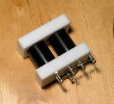
As an exercise I created the combined capacitor bracket and rectifier assembly shown below, which is for the output stage B+ supply. All I have to do now is locate and drill the mounting holes in the top plate, attach the appropriate wiring - and that circuit is done. I'm planning a similar arrangement for the driver stage supply, and also a mini version to supply voltage for the power switch LED.
Meanwhile, the wooden chassis is being sanded down after curing for a week. It's always a good idea to allow the layers of sanding sealer an extended curing period since they're applied in several relatively heavy coats. That way the excess (which is nearly all of the stuff outside the pores) sands off into a fine powder instead of a chewing gum-like mess.
Hopefully I'll get around to completing the power supply this weekend!
Meanwhile, back at the ranch... My week-long quest for a suitable insulating material has borne fruit. I've discovered: the polypropylene cutting board.
I know I said I was sold on the fiberglass board, but this stuff is great. It's flat, dimensionally stable, and doesn't retain moisture, burn easily or melt at too low a temperature. In addition it's easily worked, available locally, and - above all - cheap. But wait - there's more: did I mention that it accepts threaded fasteners easily - and that means I don't have to go out and buy craploads of extra mounting hardware? Do I hear a chorus of "heck-yessus" out there?
As an exercise I created the combined capacitor bracket and rectifier assembly shown below, which is for the output stage B+ supply. All I have to do now is locate and drill the mounting holes in the top plate, attach the appropriate wiring - and that circuit is done. I'm planning a similar arrangement for the driver stage supply, and also a mini version to supply voltage for the power switch LED.
Meanwhile, the wooden chassis is being sanded down after curing for a week. It's always a good idea to allow the layers of sanding sealer an extended curing period since they're applied in several relatively heavy coats. That way the excess (which is nearly all of the stuff outside the pores) sands off into a fine powder instead of a chewing gum-like mess.
Hopefully I'll get around to completing the power supply this weekend!
Attachments

Last edited:
the polypropylene cutting board.
I think I've seen this stuff used in some of Peter Daniels Gainclones?
Enjoying your build. Great stuff. Plenty of ideas here. Thanks for sharing
Creative cooling...
One of the things I usually neglect at this stage of a given build is to make the bottom plates. It's not that I don't believe they're needed, but I just get so wrapped up in the excitement of building that they become one of those "back burner" items. Of course they're necessary for shielding and safety, but they're not absolutely essential for an amp to function. And let's be honest here, they're usually out of sight - and quite frankly - boring.
You can see at once the flaws in this logic. Telling yourself you'll do it later is tantamount to never getting it done, and any future work is by definition a retrofit - with the attendant risk of damaging the "finished" amp. No, better to do it now and truly enjoy the finished product.
So I began by routing a "rabbet" (or rebate, if you prefer) in both bays (amplifier and power supply) to the same depth as the thickness of the plate material. Next, the material itself was cut and shaped to fit the routed area. Finally, holes were drilled in the plate to allow for cooling.
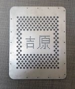
The finished amplifier bay plate is shown in the first picture. I'd originally intended to drill the entire plate with the larger sized holes, but midway through I decided to include the functionally decorative characters as an added flourish (start at Post 12 of the original thread for a more thorough explanation and translation). The second picture shows the finished amplifier bay plate in place, and the power supply bay plate being fitted. Cooling holes will be drilled in the PS plate in a similar manner, but not as many since the cooling demand will be less.
One of the things I usually neglect at this stage of a given build is to make the bottom plates. It's not that I don't believe they're needed, but I just get so wrapped up in the excitement of building that they become one of those "back burner" items. Of course they're necessary for shielding and safety, but they're not absolutely essential for an amp to function. And let's be honest here, they're usually out of sight - and quite frankly - boring.
You can see at once the flaws in this logic. Telling yourself you'll do it later is tantamount to never getting it done, and any future work is by definition a retrofit - with the attendant risk of damaging the "finished" amp. No, better to do it now and truly enjoy the finished product.
So I began by routing a "rabbet" (or rebate, if you prefer) in both bays (amplifier and power supply) to the same depth as the thickness of the plate material. Next, the material itself was cut and shaped to fit the routed area. Finally, holes were drilled in the plate to allow for cooling.
The finished amplifier bay plate is shown in the first picture. I'd originally intended to drill the entire plate with the larger sized holes, but midway through I decided to include the functionally decorative characters as an added flourish (start at Post 12 of the original thread for a more thorough explanation and translation). The second picture shows the finished amplifier bay plate in place, and the power supply bay plate being fitted. Cooling holes will be drilled in the PS plate in a similar manner, but not as many since the cooling demand will be less.
Attachments

Like the plates, very appropriate. Though, I'd prefer 'em plain drilled with same holes over. The Amp is gonna look "floating" being lit (by cathode LEDs) towards the bottom.
Hi Shef,
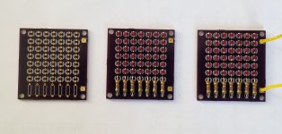
That's the idea (meaning the "floating" or "Close Encounters" look). I'd originally intended to drill them the way you suggested, but I wanted to pay homage to the "tacky" part of the original theme; tasteful tastelessness, if you will. When I first considered building this amp (about seven years ago!), I was intrigued with the idea of creating the characters with the LEDs themselves. I wasn't really certain how I'd mount them for viewing though. And besides, I'm lazy; it's just easier to order the PC boards from OSH Park and be done with it.
That said, I won't really know what the overall effect will be like or how intense it is until it's powered up for the first time. And then there's the matter of achieving the correct balance between the lower lighting and the light from the vent holes on top. Regardless, the visual output of the LED arrays is secondary to their function as a voltage source for the bias. I'm not going to whine if it's lit up like a cheap circus as long as it sounds great and measures well. 😀
I just completed drilling the PS bottom plate and I can honestly tell you I've seen enough of the drill press for a couple of weeks!
Last edited:
Hi SCD. Sorry to be MIA. I've been on extended business travel over the past month or so and haven't had much of a chance to post. Couple that with an out-of-town medical emergency and, well... Sounds kinda' like Jake's excuses, I know.
I have made some progress though, particularly on the PS side. The capacitor/rectifier module in Post 30 has been mounted and a second one built for the driver HV supply. Also, the associated 30H choke has been mounted on the underside of the PS plate using an "L" bracket. I'll try and post more pictures when I return home.
In the meantime I'm drawing up diagrams for the regulator boards, which I'm planning to build "Manhattan"-style, so stay tuned! 🙂
I'm back...
...after a long absence. Business travel... Surgery... Broken bones... Burning Amp 2017... Geez, I've gotta' get a life! 😉 But here are some pictures just to show you my heart's in the right place.
In retrospect, it seems that I backed myself into a corner somewhat regarding chassis space. The physical separation of the chassis into two bays has severely limited the amount available for the build. I normally use point-to-point techniques when I build an amp, but the RLD's relative complexity definitely calls for a different approach.
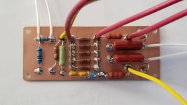
I briefly considered turret boards (a la Macintosh), but even that was going to result in a tight fit. So I decided on using a not-so-old technique from my amateur radio days: "Manhattan"-style construction. The first picture shows the beginning of the build for one of the two boards that will house most of the audio circuitry. Note the array of five 665k resistors: Mouser was actually out of the correct value for the phase inverter load resistor, so I improvised.
The second photo shows the completed assembly, ready to mount. All I have to do now is connect each of the wires to its corresponding socket pin and I'm ready to go.
...after a long absence. Business travel... Surgery... Broken bones... Burning Amp 2017... Geez, I've gotta' get a life! 😉 But here are some pictures just to show you my heart's in the right place.
In retrospect, it seems that I backed myself into a corner somewhat regarding chassis space. The physical separation of the chassis into two bays has severely limited the amount available for the build. I normally use point-to-point techniques when I build an amp, but the RLD's relative complexity definitely calls for a different approach.
I briefly considered turret boards (a la Macintosh), but even that was going to result in a tight fit. So I decided on using a not-so-old technique from my amateur radio days: "Manhattan"-style construction. The first picture shows the beginning of the build for one of the two boards that will house most of the audio circuitry. Note the array of five 665k resistors: Mouser was actually out of the correct value for the phase inverter load resistor, so I improvised.
The second photo shows the completed assembly, ready to mount. All I have to do now is connect each of the wires to its corresponding socket pin and I'm ready to go.
Attachments

Last edited:
- Status
- Not open for further replies.
- Home
- Amplifiers
- Tubes / Valves
- Red Light District - Build Thread