Hi Everyone,
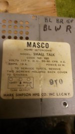
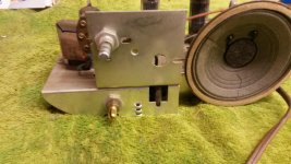
I'm new to this forum and mostly new to DIY audio. I took an electronics course in high school and really enjoyed it. Unfortunately that was in 1996 and I haven't done much, other than the occasional repairs here and there, since then. I recently discovered an old Tube intercom in my in-laws basement. And from what I can tell, it still works. It powers up, the tubes glow, and when I adjust the volume pot, I get an increase in hum that I can only assume comes from no input signal. What I would like to do is turn this dusty old relic into a small guitar amp. I can't seem to find a schematic on it so I'm a little lost. I'm not sure what components (if any) I should remove or bypass. I also need to replace the old speaker. It's very brittle. I gouged a rip in it just taking the chassis out of the case. I took as many pictures as I could, and I would dearly love some help on this. I think it will make a great retro guitar amp when I'm done. Thanks ahead of time!
I'm new to this forum and mostly new to DIY audio. I took an electronics course in high school and really enjoyed it. Unfortunately that was in 1996 and I haven't done much, other than the occasional repairs here and there, since then. I recently discovered an old Tube intercom in my in-laws basement. And from what I can tell, it still works. It powers up, the tubes glow, and when I adjust the volume pot, I get an increase in hum that I can only assume comes from no input signal. What I would like to do is turn this dusty old relic into a small guitar amp. I can't seem to find a schematic on it so I'm a little lost. I'm not sure what components (if any) I should remove or bypass. I also need to replace the old speaker. It's very brittle. I gouged a rip in it just taking the chassis out of the case. I took as many pictures as I could, and I would dearly love some help on this. I think it will make a great retro guitar amp when I'm done. Thanks ahead of time!
Attachments
First, you want to get an isolation transformer to run this - as it is, there's no isolation between the wall socket and the chassis. This is unsafe and potentially lethal.
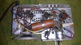
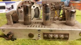
In the second picture, the tube on the left is 50DC4 50DC4, Tube 50DC4; Röhre 50DC4 ID5782, Half-Wave Vacuum Rect a 7 pin half wave rectifier with a 50 volt heater. The center tube is a 50C5 pentode 50C5, Tube 50C5; Röhre 50C5 ID1071, Beam Power Tube and the rightmost tube is a common 12AX7.
Is there a transformer on the other side of the chasis? I doubt there is, the speaker is probably an odd impedance like 2.5K and is used as the anode load for the 50C5.
First off, your welcome.
To convert it into a guitar amp you will need a 120V to 120V isolation transformer, if you are not familiar with one,
Widowmaker? | Lectrolab Guitar Amplifiers
Next go to this page,
50C5/35W4/12AU6 amplifier problem in Sears intercom- no sound - AudioKarma.org Home Audio Stereo Discussion Forums
Should tell you all about your unit. You will probably have to replace that big capacitor. There is two in there, you can get two single caps easier than a replacement. Here is another amp.
Oops, did not notice the 12AX7.
http://www.kirtland.com/guitar1/MA1_files/50L6_Amp-1.gif
http://www.tdpri.com/forum/shock-brothers-diy-amps/369411-sparton-aa5-clock-radio-guitar-amp-2.html
Last edited:
Hi,
As an intercom the speaker is also the microphone and very
likely high impedance. It won't make a decent guitar amplifier
and it is downright dangerous, probably illlegal nowadays.
rgds, sreten.
As an intercom the speaker is also the microphone and very
likely high impedance. It won't make a decent guitar amplifier
and it is downright dangerous, probably illlegal nowadays.
rgds, sreten.
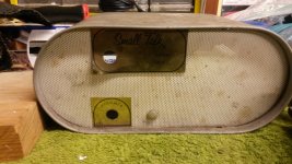
The amp is lethal, the speaker is useless, but that case is very cool.
Gut it and rebuild. a 12ax7 and a 6bq5 power tube would fit it that
chassis. A solid state rectifier will save you some space. Find a suitable
power transformer and use and external speaker. You can measure the
specs on the output transformer but I doubt it will be suitable. Great find.
I want one now.
Yeah, from all the material I've been reading on the past few hours (thanks guys! I couldn't find information like this anywhere!) The best thing I can do is gut it and start over. I may look into buying a kit to build when I get some money. I appreciate everyone's help! If I get it built I'll be sure to post pics.
The speaker might be salvageable with something like this:
Wet Look 4 oz. Black
The output transformer is probably OK. The mic/speaker transformer could be scrapped and an isolation transformer put in its place, like this:
https://edcorusa.com/pwrc120v0_3a-1
(and don't forget to add a fuse!)
At a minimum, the capacitors need to be replaced with new ones. The resistors could stand to be replaced since I've seen old carbon comp resistors like those vary as much as 300% when they age. At this point, you're talking a complete re-wire, including safety earthing the chassis. I'm not sure if keeping those tubes makes much sense, but it could be done. The previous linked schematics are a great start, but if you don't have much experience, you definitely need lots of help from someone who knows what they're doing. Tube amps can be lethal if proper care isn't taken.
If done right, it looks like it could make a nice little guitar amp.
I say make the amp in the cabinet and get a speaker in its own box. Use the tubes and output transformer you have, not like it is costing you anything. Get a cheap transformer like this one.
Search results for "N68X" - Allied Electronics
This is your learning amp, I would stick with it. If you want to go farther after this amp, you can use the isolation transformer for your high voltage supply, use a 6V or 12V transformer for your heaters and end up with a 15W amp depending on what you chose. Use the sockets where they are and do a point to point build.
The output transformer probably has about a 2k ohm impedance given the tube used, maybe one watt.
Yeah. I think I'm going to build it as a stand alone. Use a separate speaker cabinet. I don't need it to do a whole lot. just saw it in a box of junk and thought "wow! that would make a cool little practice amp!" I'll keep doing my research and see what happens. This is definitely changing into more than a weekend project. I've had experience with tubes before. My 12 grade class project was a rebuild of a 1937 GE console stereo with record player. I found it in an abandoned barn and rebuilt it. But it was back in 96 and I had access to many tools I can't get now. Tube testers, oscilloscopes, things like that. Not to mention my class teacher was a true genius!
I am not a fan of these daisy chain style amps even with an isolation transformer.
You can easily build something much better with existing chassis and tube sockets.
Find a 7 pin power tube and rectifier that will run on 6.3v heaters with your 12AX7.
You can easily build something much better with existing chassis and tube sockets.
Find a 7 pin power tube and rectifier that will run on 6.3v heaters with your 12AX7.
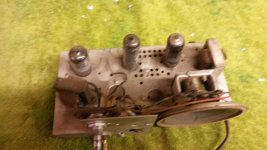
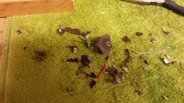
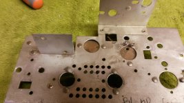
Unfortunately some sad new today. After starting my De-soldering process, I noticed some charring on the chassis around the tube sockets. When I started removing components from the sockets, they turned to dust. Quite literally. Good news is, I have a clean chassis now! But now that basically nothing is salvageable, I don't know where to go next. I may try and build a solid state PCB to mount to it instead. So many options, not enough money haha.
Attachments
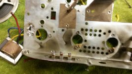
Well the sockets are history, so that opens up a lot of possibilities. Drill out the rivets and install 9 pin sockets and make an EL84 (6P14P) amp using the existing output transformer and a new power transformer. Use solid state rectification and a CRC filter, maybe a zener based regulator on the pentode screens or triode strapping...the possibilities are endless.
The web page Printer2 linked to explained the reasons amps without power transformers are called widowmakers. It then asked if Lectrolab ever made a widowmaker. I can confirm that they did. I got a grey Lectrolab amp in an antique shop for $10. I have long ago given it away, but I believe it had a 50C5 output tube, a 35W4 rectifier, a 12AU6 input tube and a 12AT6 driver tube. It was powered directly from the line voltage, s0 I added a Triad N68X isolation transformer, changed a few caps and a couple of resistors, and it was alive.......for about 10 minutes. It took me about that long to turn that 60 year old speaker cone to dust.
It took me about that long to turn that 60 year old speaker cone to dust.

I have a tweed danelectro widowmaker with just 12au6, 50c5, and a 35w4 and I love it. Anyways, now you can rebuild the amp from scratch. I'd recommend a 6AU6 pentode preamp into a 6aq5 output with a solid state rectifier. For more gain you could add a 6av6 triode-dual diode tube. Maybe you could even use the internal diodes for clipping or to run a VU meter.
I'd recommend a solid state design if this is your first time building an amp; tube voltages are lethal which makes troubleshooting very hard.
Get a few cheap vertical mosfets, some 2n3904s and 2n3906s, assorted resistors and capacitors, some wires, and a prototype board.
Then choose a simple design, for example the CIRCLOMOS or my design. Build it on a breadboard first and power it with a pc/laptop power supply or any other power supply that has built in current-limit circuitry. You may need to make customizations to the design to make it work with the lower voltages.
After testing the design on a breadboard, move it onto the prototype board.
- Status
- Not open for further replies.
- Home
- Live Sound
- Instruments and Amps
- recycling old tech to make an amp