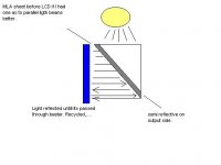
Now I have looked into this lightly but I'm sure wome of you have beeter idea of how this works. I know that htey use MLA and prism to use waisted light. How to repolarise light is beyond me but none the less. What kind of prism do you need to do this? I have found 90o deflection prisms that have a reflective surface on one end (anodized). So would this kinda work?Would light coming from a prism be more parallel? Any ideas or sugestions are more than welcome. I think we have to find some way of atleast partially recycleing our loses with light. THis will be a big help. I'm sur with all of us we can do somthing, maybe not like the big boys are getting but atleast somthing to help with light losses.
Attachments
Tinker
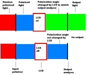
The attached image shows the LCD only uses polarised light.
For clarity I have shown the input polariser, and the output analyser separate from the LCD but they are glued onto the lcd
The input light (red) on the left contains random polarisation. Since the LCD can only use one polarity much of the random polarised light is wasted ie blocked from continuing by the input polariser. Light can be resolved into a P polarisation and an S polarisation. LCD use the P polarisation. The S polarisation component is totally wasted because it cannot go through the input polariser.
Obviously loosing half the light is a big loss but techniques to recycle the lost light are not simple.
If we could pass the input light through a polarisation splitter first, allow the P polarisation to continue, change the waste S polarisation to P polarisation then redirect that light onto the input polariser it would also pass thus we would be using all the input light instead of half as we do at the moment.
One method is to use a semi transparent 45 degree mirror in the input light path with a polariser. Half the light goes through the 45 degree mirror. The half that is redirected by the mirror hits a polarisation changer, then another mirror sends that through to the lcd. So the LCD is illuminated in two halves. The left hand half by correctly polarised light and the right hand half by modified polarised light. Both halves of the LCD are now getting correctly polarised light and there is a much smaller fraction of wasted light.
MLA are not used in the polarisation recycling. They are used just before the LCD to straighten the light beams so they pass through the panel more parallel which reduces waste light scatter and increases contrast. A sheet of MLA is not cheap.
If you want to look into this further try the United States patent data base and search for "LCD projectors" then look at the latest ones. There have also been discussions in video projectors part 1
Attachments
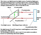
The diagram shows a typical polarising cube beam splitter. Reference Patent 6206532. These units illuminate the LCD in two halves and there may be minor variations between halves which can be corrected by filters. Apparently only suitable for small LCD sizes.
Other patents dealing with recycling light.
6411438, 6404551, 6394607, 6339454
To combine the S and P polarisations into one homogenous beam, 3m have a thin sheet polariser which is described below. Since the patent description describes the light situation with respect to LCD illumination and expected efficiency it has been left intact as a reference text
*************************
Reference 3m patent 6104536 thin sheet polariser.
The present invention relates to a polarization converter that efficiently converts substantially normally incident unpolarized light into linearly polarized light. More specifically, the present invention relates to a relatively thin lenticular polarization converter and to liquid crystal display (LCD) projection system designs including the novel thin polarization converter, for example, full-color LCD projection systems.
Polarization dependent spatial light modulators, such as some LCD devices, require polarized light. Two challenges in designing polarization converters for use with LCD devices are compactness and efficiency. A compact planar polarization device that efficiently converts unpolarized light to polarized light would aid greatly in the design of compact and portable LCD devices.
Unpolarized light may be decomposed into a linear s-polarization component and an orthogonal p-polarization component. A method for producing polarized light for a LCD projection panel comprises the use of a polarizing beam splitter (PBS) cube or rectangular prism. One linearly polarized component of the light is transmitted by the PBS cube and directed to the LCD panel, while the orthogonal component is reflected away in a perpendicular direction. Other devices use non-cubic polarization splitters (non-rectangular prisms). Both the cubic and the non-cubic devices have a considerable longitudinal dimension (in the direction of travel of light) in relation to its transverse dimension. (An exemplary device has thickness dimensions that are approximately one fourth of the width dimensions.)
Another common method for producing polarized light comprises the use of an absorbing dye or iodine based polarizer film positioned between the light source and the LCD panel. The absorbing film transmits a single component linear polarized light, while absorbing the orthogonal component. Accordingly, the maximum conversion efficiency that may be achieved with an absorbing polarizer is 50% or less. The absorbing polarizer film is often integrally incorporated into the commercial LCD panel. Alternatively, a separate polarizer plate may be positioned between the light source and LCD.
Both a plain PBS cube and an absorbing polarizer are inefficient, in that a maximum of only one-half of the available light from the source is converted to polarized light for transmission through the LCD panel. Attempts have been made to recycle the reflected polarization component from a PBS cube. However, solid glass PBS cubes are bulky and impractical for applications in which the diagonal of the spatial light modulator exceeds approximately 50 mm.
Some existing polarization converters include lenslet arrays followed by a polarizing component. The lenslet array commonly includes an array of "Galilean telescopes", that is, the first surface of the array has convex lenslets that focus the light and the second surface has concave lenslets to recollimate the light. The lenslets on the second surface are smaller than those on the first so the intervening spaces can be used to convert the light from one polarization state to another. The component that converts the polarization state is always in the light path following the recollimating lenslets.
Recently, reflective polarizing sheet films have been developed. Use of a reflective polarizing sheet film, instead of an absorbing sheet polarizer, allows for the possibility of reflecting back the s-polarization component of a light beam in the direction of the light source. Methods have been described that return the reflected polarized light to a reflector behind the light source, and back to the LCD panel. However, these methods require extremely precise alignment of the optical components for efficient recycling of the light and are not easily suitable for compact applications.
FIG. 1 illustrates a polarization converter 10 depicted in U.S. Pat. No. 5,566,367. A beam of incident unpolarized and collimated light 70 is compressed into collimated sub-beams 72 by a lenticular element 20. The lenticular element includes an entrance surface 22 and an exit surface 30. The entrance surface is comprised of converging lenslets 24, while the exit surface has diverging lenslets 34. The resulting sub-beams 72 are incident upon a prismatic element 40. Linearly polarized beams 74 exit
Attachments
Thanks remp, thats more info than I could have hoped for. Your great!!! So we could build this? I mean it doesnt look that bad to make. its a matter of parts and price really. The componenet list is:
Birefringent layer reflector
1/2 wave plate
standard flat mirror
Mirror is easy but where to get the other two is the prob. I'll have to search and see what I can come up with. The Birefringent layer reflector is just like those color mirrors that reflect all colors except one that passes on. Just this reflects undesired waves and passes the right ones. Then the 1/2 wave plate changes their direction of movement thus changeing the polarisation, I see know. I have a 5" panel so size shouldnt be the prob. for aligning the light on each half of lcd. I really wanna try experimenting with this theory, have to dig up the parts some wheres. On another note, I have my brother looking into some light traceing software and how to do it correctly. He's a CAD engineer so these prog.s make more sense to him than I. Hopefully he can add a little profesionalism to my deseign. He will be a great help with aligning the lenses and such as he's drafting out my hole layout of projector for me. So everything should be nice and centered.
P.S. I was reading some of the theorys about light and light waves to understand this better. What about the theory that light reflected by a metal polished surface (or mirror) are polarised. Arent they polarised though both ways, and we need only one. Which brings me to next question, which polarisation do we need? Also does the magnetic polarisation have any effect on its use by panel. I know there are two types of polorisation. One which is movement of wave of light, other is magnetical. Thanks you have been loads of help!😀
Tinker
Here is an extract from google search polarized light =Alaska science forum regarding polarization from surfaces.
Now suppose the sun is somewhat above the western horizon, with a smooth water surface at the ground. Some of the light will penetrate into the water and some will be reflected. But if we look in more detail, it turns out that the electrical fields that are vibrating in the surface of the water (north-south) have trouble penetrating the water and are mostly reflected, while those that are partly perpendicular to the water penetrate easily and produce only a little reflection. As a result, both the reflected light and the light entering the water become polarized, which simply means that one direction of vibration of the electrical field dominates. Most of the light reflected from a horizontal surface will have its electrical field horizontal, and we say the light is horizontally polarized. Ice, glass, or any other polished surface that does not conduct electricity behaves the same way. (Metals, which do conduct electricity, do not polarize light on reflection.
LCD's use either P type or S type depending on manufacturer.
Testing light for polarization use a polarizing filter from most photographic shops. Small piece of film is about $2.
Light has an electric field and a magnetic field. Most use is of the electric field. It is extremely difficult to affect a light beam by any magnetic fields that humans can arrange.
Attached diagram shows how a randomly or unpolarized light source can be resolved into P and S polarization.
Attachments

- Status
- Not open for further replies.