Been a while since I've been here, just looking for a bit of verification on my current problem. I have an Auna Concept 620 which has been acting up lately, a lot of noise on the channels at times, audio just not coming out at random, other times audio being extremely quiet even with the sub volume at maximum, that kind of thing. I'm fairly certain the problem is with the 1N5404 rectifiers and considering they are on the edge am wondering if I should replace them with some 1N5408s to handle things better or if anyone could suggest something else? My only focus is with building something that is extremely robust - specs mean nothing to me if I won't have an audible difference.
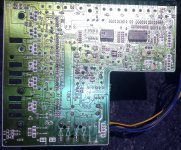
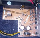
Years ago I did some major recapping work on the sub where the primary capacitors blew out (I wasn't surprised to see this when I saw how severely under spec they were) so those got replaced with 2x 25v 125c RS brand capacitors and all other caps were replaced with Rubycon and Nippon Chemi-Con 105c so I know all of those caps are good but to be sure I did also inspect them, no leaking or bulging I can see. Any extra input is appreciated, I've attached a few images of the patient.
EDIT: On another note why is it the text size is appearing like it is set to extra large on the forum and it won't change when I select other sizes?
Attachments
Last edited:

@ejp I'd describe it as more of interference hum, kinda like there's a lot of electronic cross talk from inadequate shielding\filtering or maybe resistance somewhere isn't what it should be, something like that. I've tested with different cables and got the same results so can rule those out and earlier theorizing I did swap the position of a couple of the rectifiers and used new solder in case the issue was simply some bad joints and also thinking if the rectifiers are bad heating them up should make them temporarily function normally and this does seem to be the case the sub has worked normally today for several hours.
The transformer in the subwoofer is pretty beastly (its an Enkoor, I can get specs later if needed) so given the age and borderline adequate for spec nature of the rectifiers is why I'm suspiciously looking at them with one eye as I didn't replace them when I did all the recapping work so can't rule out when the nasty cheap no-name caps blew it also shortened the life of other components. If you have any other ideas I'm all for investigating that.
The transformer in the subwoofer is pretty beastly (its an Enkoor, I can get specs later if needed) so given the age and borderline adequate for spec nature of the rectifiers is why I'm suspiciously looking at them with one eye as I didn't replace them when I did all the recapping work so can't rule out when the nasty cheap no-name caps blew it also shortened the life of other components. If you have any other ideas I'm all for investigating that.
Why? Normally cooling things down makes them work if marginal.if the rectifiers are bad heating them up should make them temporarily function normally
You seem to be clutching at straws here.
It's to do with the flow of electrons through components why heating them can temporarily restore normal operation, cooling components slows the flow of electrons. TWhy? Normally cooling things down makes them work if marginal.
You seem to be clutching at straws here.
there's more to it than that but I forget the exact specifics. The fault could be with one of the PCB traces but as yet I've not found anything I'll be looking closer at that when a few components turn up to do it all at the same time. I've ordered some 1N5408s anyway they aren't expensive and it's the only way to 100% rule them out, I also have never liked the quality of the original components in the sub so it's no loss either way just an improvement on the road to looking at practical fixable elements.
Where are you getting all these misconceptions?It's to do with the flow of electrons through components why heating them can temporarily restore normal operation, cooling components slows the flow of electrons.
Ok folks, an update on the situation I didn't see much point in posting back without any real info. I went ahead and got some 1N5408s and installed them, seems like the rectifier diodes were to blame as there's been no issues over the last few days so we can assume the issue resolved but if I can I would like to improve the sub performance by getting rid of (if possible) a slight electronic hum that comes through. This Auna 620 set has always had it and as I've pretty much gone and replaced 60% of the original components on the PCB at this point I figure if there is a way to get rid of this slight hum I might as well. I assume it's likely a case of filtering but I'm not sure where I would need to add it as stuff like subwoofer repair isn't the usual kind of electronics I fix. Anyone have any ideas what I'd need to do to resolve the humming?
Just did a quick google search, and going by the specifications, you should be fine with substituting 1N5408 diodes for the 1n5404 diodes, the 1n5404 is rated at 400V PIV (Peak Inverse Voltage) at 3A, whereas the 1N5408 is rated at 1000V PIV at 3A, the PIV rating of a silicon power diode is the maximum reverse voltage that the diode can withstand before being destroyed.
With regards to the hum, you could check the condition of all the supply filter caps to see if none of them have started to go leaky or have developed a small bulge in the rubber sealing bung, if you do find any that look suspicious, change them out for new ones of same ratings as the originals, you might have also inadvertently created a ground loop which could be causing the hum.
With regards to the hum, you could check the condition of all the supply filter caps to see if none of them have started to go leaky or have developed a small bulge in the rubber sealing bung, if you do find any that look suspicious, change them out for new ones of same ratings as the originals, you might have also inadvertently created a ground loop which could be causing the hum.
@DrNomis44 the original rectifiers were 1N5404s that I replaced with the 1N5408s as one of them at least seemingly had gone bad and as they were borderline spec-wise I figured might as well go with the 5408s as at worst they will just handle any scenarios like transient spikes better. The capacitors on the PCB I've replaced with Nippon Chemi-Con and Rubycon as well as beefed up the 2x main caps to 25v each to rid the sub of what used to be an awful "pop" whenever it was switched on at the back and I have checked all of the caps - no leaking or bulging, which is why I thought the issue might be a lack of filtering. A ground loop is a possibility though as I've looked at a few different Auna Concept 620 PCBs on Ecosia where I found a lot of shoddy solder work on mine but the other boards I've looked at are all slightly different with the soldering, mainly to do with the bridge rectifiers. One picture had all of the holes filled and the other didn't. Mine had 2 filled and 2 not so I'm not sure whats meant to be correct for this PCB. I guess the only way to find out will be to remove that bit of solder and see if the hum gets better or worse. TBH to my eye as someone who isn't used to fixing audio PCBs the board looks rather poor and cheaply made so it could be an inherent problem with the cuircut. I've got a replacement digital camera on the way so I'll be able to get much better pictures of the PCB my sub has in a few days.
You could also try re-wiring all the grounds to a star-grounding system, doing that may help to reduce the hum, it's possible that the grounds on the pcb may not have been optimally laid-out if the pcb is of cheap quality, from what I've read in some online articles, good ground wiring is important for low-noise in amplifiers, a lot of people don't realize that even though a piece of wire has low resistance, it can still develop a voltage-drop across it when current flows through it, as does a resistor, and it's that voltage drop that induces hum noise in a circuit, wiring the grounds in a star-ground system helps to eliminate that, do a search for an article on circuit grounding by Merlin Blencowe, a really good and informative article.
Blindly adding parts or re-arranging ground schemes is not the best solution. Noise and intermittent volume is more likely a bad solder joint than "borderline" diodes. Measure the voltage while the amp is acting up, does it change any? Lack of filtering will produce 120 or 100hz ripple on the output. First determine what actual problem you are encountering.
Does it hum with no interconnect cable plugged in at all?
Does it hum if you short out the input?
Is the hum 120Hz or 60Hz (50Hz or 100Hz depending on country)?
How long is the interconnect cable?
Does the signal source have a safety ground or is it a two prong?
Is the signal source a receiver with many other sources connected?
It may just be a ground loop somewhere with the source interconnect ground(s) and safety ground(s), a common problem subs often face. Easiest solution for subs with a ground loop issue is an isolation transformer. Jensen ISO-MAX for subwoofers is a good one:
https://www.jensen-transformers.com/product/sub-1rr/
ket,
Measure the hum (100uV, 1mV, 10mV, etc.).
Is it just one frequency? Or two frequencies (such as power mains frequencies, plus 2 x power mains frequencies)?
A complete and accurate schematic might save running this thread count to 100.
Ground the grids of the output tubes. Caution: if the grids are at other than 0V (like fixed bias), ground the signal to the grids with a capacitor.
Move to the next earlier and ground its grid (DC or AC according to the grid voltage).
Move to the input stage, ground its grid to the bottom of its cathode' self bias resistor.
At which setups above does the hum not go away?
Then start looking at the B+ ripple for each tube . . . Hum
Output transformer angular orientation and distance . . . to the power transformer and the B+ choke . . . Hum
Magnetic Steel Chassis . . . Hum
When you fix one cause of hum, often you find another cause of a lower amplitude hum.
Process of elimination.
Last edited:
- Home
- Amplifiers
- Tubes / Valves
- Rectifier Diode Replacement