I'm building a class D amplifier, switching at about 360kHz (adjustable), and am looking for a good circuit to convert square wave pulses into a clean, linear triangle wave.
Currently I'm just integrating using an AD8605 (feeding a MCP6561T comparator), but I think there is probably a better way? In particular, better linearity would be ideal, as would a more uniform triangle amplitude vs. frequency.
Currently I'm just integrating using an AD8605 (feeding a MCP6561T comparator), but I think there is probably a better way? In particular, better linearity would be ideal, as would a more uniform triangle amplitude vs. frequency.
GBW product and Slew rate. Drive impedance to the integrator. Place a DC servo around the integrator. Modulate the drive to the integrator based on the power stage supply voltage AKA voltage feedforward.
Thank you! I understand GBW and Slew rate requirements of the opamp, I think my selection is OK (as is the LTC6244 I was also considering). Regarding the rest, I have a vague idea what you are talking about, but I'm afraid I don't understand it fully. Do you have an example somewhere? (Surely this is a well known circuit?)
If it's helpful, I'm using a single-ended 3.3V supply for the signals, and 24V for the power stage. (H-bridge)
If it's helpful, I'm using a single-ended 3.3V supply for the signals, and 24V for the power stage. (H-bridge)
Last edited:
I think that you should probably be looking for a faster comparator -- see section 3.2 of this application note from Texas Instruments: http://www.ti.com/lit/pdf/slau508
I think that you should probably be looking for a faster comparator -- see section 3.2 of this application note from Texas Instruments: http://www.ti.com/lit/pdf/slau508
Thanks, I'll look into that as well. I still need a better triangle. 🙂
Basically a version of the 555 with massive bandwidth would be handy 🙂
I wonder what the best way to measure/assess triangle wave quality is without expensive test-gear? Just a precision differentiator into a 'scope?
I wonder what the best way to measure/assess triangle wave quality is without expensive test-gear? Just a precision differentiator into a 'scope?
Basically a version of the 555 with massive bandwidth would be handy 🙂
I wonder what the best way to measure/assess triangle wave quality is without expensive test-gear? Just a precision differentiator into a 'scope?
My square wave is very clean, I don't need to worry about that... Converting it to a triangle is what I need help with.
I was going to examine the spectrum, as well as final thd, to assess accuracy, though a straight edge against a scope might also work pretty well. 🙂
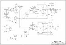
Here is a pic of how I did it, using a opamp as integrator.
Nice!
Here is a pic of how I did it, using a opamp as integrator.
Thanks! Seems comparable with mine, maybe I don't need to go crazy with it. I was hoping for more elaboration from Morbidfractal though.
I used the double ended output from CD4047 to get double amplitude, butit is not needed, Using single ended, the NI input need to go to signal ground, but taking into account DC levels for future stages. This is why I put the offset adjustment there. Note the blue trimpot.
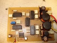
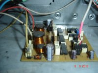
Here is a pic of the amp inside my workbench PC.
Here is a pic of the amp inside my workbench PC.
Attachments
Thanks! Seems comparable with mine, maybe I don't need to go crazy with it. I was hoping for more elaboration from Morbidfractal though.
Not sure there is much more I can add. You sound happy with your choice of opamp and comparator. It exceeds the required slew rate by a factor of two. Whether that is enough? GBW is how many harmonics of your triangle wave you want to faithfully produce bearing in mind that the go down in amplitude according to some power law.
Drive impedance might be worth considering. I assume you are using (H)CMOS and scale the integrating resistor accordingly. Parallel gates. Whether PMOS vs NMOS on resistance is an issue is another one. Transition speed may not matter too much in as much as that will affect peak linearity where your amplifier is likely to be in clip anyway.
You might consider putting a DC servo another, low frequency, integrator around the triangle integrator rather than shunting the integrator capacitor with a resistor. That might cause stability issues given the second order nature of the resulting loop. Do it inverting and drive the non-inverting input of the triangle generator to make use of Av = 1 + therest, adds a zero, but check, in spice, to make sure.
Voltage Feed Forward, VFF. Make the supply to your square wave output logic proportional to the power stage supply. Again with (H)CMOS this should not be hard to do. It's good from 1.5-6V which is probably much more than you need. The square wave amplitude will vary with the supply amplitude and as a result the triangle wave amplitude will do the same.
Gain of the modulator is proportional to 1/Amplitude. Gain of the power stage is proportional to Supply. The idea is that the changes cancel. If you include integrating feedback, pre-filter, then you have to slope match according to the minimum triangle slope.
Given things will be going up and down there will be a bit of thought required as to what you feed where and how it might get referenced to each other to avoid upsetting the whole apple cart.
Got it thank you! I'm certainly fine with upgrading the opamps and comparator, and I understand those implications, it was the servo and VFF that was unfamiliar, as I've never encountered those before.
If there are any references online or in books to similar circuits, that would be great, but I really appreciate the more thorough explanation regardless.
If there are any references online or in books to similar circuits, that would be great, but I really appreciate the more thorough explanation regardless.
I came across this article in EDN -- using a CMOS inverter greatly enhances the integrator's effective ability to source current (original article): https://www.edn.com/high-fidelity-triangle-wave-generator-consumes-only-6-µa/
Article with schematics: High-fidelity triangle-wave generator consumes only 6 mA
Article with schematics: High-fidelity triangle-wave generator consumes only 6 mA
Last edited:
- Home
- Amplifiers
- Class D
- Recommended Triangle generator circuit (from square pulses)