Just out of curiosity, how did you come to this circuit? There's some features that seem... odd. Your cartridge will not be happy. The gain is likely to be extremely low and conformance to RIAA will be problematic.
http://www.tubecad.com/2007/08/blog0116.htm
Best for MC carts as the input impedance of this unit is insanely low. The schematic is incomplete as I will be adding an input transformer for MC carts. I will post the MM version in a few.
Best for MC carts as the input impedance of this unit is insanely low. The schematic is incomplete as I will be adding an input transformer for MC carts. I will post the MM version in a few.
Last edited:
Interesting circuit... If the cartridge needs to be loaded anyways, why not use the cathode impedance to do it?
I particularly like JB's thought to use a transformer as the cathode resistor to ditch the huge coupling cap.
dave
I particularly like JB's thought to use a transformer as the cathode resistor to ditch the huge coupling cap.
dave
Thats the whole idea. Are there transformers that can match MM carts to the low impedance, or will I need to custom here?
Assuming you have enough gain / low enough noise to do MC direct (Tina will tell you that) i see no reason why you couldn't use a 500:50K mic transformer in reverse. It is sort of a fun idea using a MC stepup in reverse.
dave
dave
Will try that. MM's should be OK on the noise. MC direct will be too noisy unless a stepup transformer is used.
I like the idea of balanced phono stages but moist turntables use RCA and not XLR unless you modify them. That will void the warranty totally on my new unit.
I like the idea of balanced phono stages but moist turntables use RCA and not XLR unless you modify them. That will void the warranty totally on my new unit.
You have to understand that this stage will provide about a 450-500R load to the source so any step up device will take that value lower. A 1:4 ratio quickly brings you to 30 ohms so apply your SUT's carefully. Using a transformer in the other direction to bring load up to MM levels (47K) will require that the stage be quiet at MC levels. Essentially I don't think you can win both battles with this design unless it is quiet enough for MC without a SUT.
Maybe you need to look for a pair of Telefunken ECC 803S's 🙂
dave
dave
Maybe you need to look for a pair of Telefunken ECC 803S's 🙂
dave
dave
You really can't make an RIAA curve unless you can change gain by 40dB from low to high frequencies. Non-inverting feedback can't reduce gain below 0dB, so you have to start with quite a lot. There're reasons phono equalizers are made with several gain stages.
All good fortune,
Chris
All good fortune,
Chris
Oh dear.
Look, MJ is cool and all, but don't go copying circuits wholesale if you can't read Japanese.
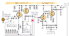
JB was wrong about the circuit. The red "X" he marked to indicate what he thought was an incorrect connection is itself wrong. The circuit is correct as originally drawn, the connection does not short to ground, it appears to set the gain, connected as it does to the "MC gain switch".
The left and right halves of the circuit are maked "MC head amp" and "Phono EQ amp" respectively. The RIAA network is right there in the circuit, bottom right, where is says "NF型EQネットワーク". The key point here is the MC/MM switch only engages the low impedance "grounded grid" input stage when MC cartridge is selected, MM carts are routed directly to the second, high impedance second stage.
Don't use the "MC head amp" circuit with a MM cart, you will be completely screwed...
Look, MJ is cool and all, but don't go copying circuits wholesale if you can't read Japanese.
JB was wrong about the circuit. The red "X" he marked to indicate what he thought was an incorrect connection is itself wrong. The circuit is correct as originally drawn, the connection does not short to ground, it appears to set the gain, connected as it does to the "MC gain switch".
The left and right halves of the circuit are maked "MC head amp" and "Phono EQ amp" respectively. The RIAA network is right there in the circuit, bottom right, where is says "NF型EQネットワーク". The key point here is the MC/MM switch only engages the low impedance "grounded grid" input stage when MC cartridge is selected, MM carts are routed directly to the second, high impedance second stage.
Don't use the "MC head amp" circuit with a MM cart, you will be completely screwed...
Attachments
Last edited:
This is the basically Circuit that involve the Transistor based "phonoclone" system but you can specify it's consumption of input Volatage. you are also not specify the configuaration of all components which are you use in this.
Oh dear.
The left and right halves of the circuit are maked "MC head amp" and "Phono EQ amp" respectively. The RIAA network is right there in the circuit, bottom right, where is says "NF型EQネットワーク".
I am a Japanese. rjm is correct.
The correct NF equalizing CR values are indicated in the following Web
(sorry written in Japanese but you can read the schematic).
It is noted that the first stage of 12AX7 is for MC head amp which
you can eliminate for MM cartridge.
Tube Pre
I can't quite work out what this circuit is for. It clearly is not for MM as the input impedance is far far too low. It clearly is not for MC as the input noise is far too high. It clearly is not intended to have accurate RIAA equalisation as the open loop gain is insufficient and depends too much on valve parameters.kingneb said:Hi, I have a circuit I came up with that uses a grounded grid feedback configuration.
Was someone running a competition for weirdest use of a 12AX7, but nobody told me?
Well, that was (for once!) a less polite version of my comment. 😀 It's a circuit which solves a nonexistent problem (whatever it is) with conventional MC amps by introducing far worse ones.
I don't often say this, but Broskie's analysis here is way off base.
I don't often say this, but Broskie's analysis here is way off base.
It seems to me that the ultimate best way to accomplish low noise MC amplification is a fully balanced phono preamp. My turntable is a Clear Audio Concept unit. It has permanently attached RCA cables so modifying the unit will void the warranty.
As far as tube parameters go for RIAA, it seems that a cathode follower is the best way to combat that problem. Other designs I am experimenting with are hybrid op-amp/12AX7.
As far as tube parameters go for RIAA, it seems that a cathode follower is the best way to combat that problem. Other designs I am experimenting with are hybrid op-amp/12AX7.
Last edited:
The circuit as shown will also have an input impedance which varies with frequency, due to the RIAA network. The original Japanese circuit shown by Broskie does not have this problem. Even with that, I find the idea of a grounded-grid 12AX7 rather unusual for MC - I would have thought that the noise and impedance would be too high.
I have never used MC but I suspect that for that you either need BJTs or a good transformer.
I have never used MC but I suspect that for that you either need BJTs or a good transformer.
The equivalent noise resistance of a 12AX7 in the audio band is on the order of 1k-2k, so indeed, it is far too noisy for MC circuits. Input transformers are your friend here, but the need for grounded grid is unclear in an MC application (which doesn't have an MM's sensitivity to input capacitance).
Given that 2.5/gm ignores 1/f noise I would expect rather more than 1-2k ENR for audio. I'm sure I have asked this before: roughly where is the 1/f corner frequency for a typical triode? I seem to recall maybe 10kHz-ish?
For an MM preamp article I've been working on, I measured the ENR of some 12AX7s (actually Mullard and Telefunken ECC83), and that was the actual spread. Voegel's recent article in Linear Audio showed a LOT of variation in corner frequency and had little to say about predicting it.
OK. That would imply that 1/f is generally small for those valves. Of course, the 2.5 in 2.5/gm is only an average figure as it depends on the details of the triode geometry.
I once read somewhere (can't remember where) that European cathodes were generally better made than US cathodes so had lower 1/f. Not sure if this is true or just the usual transatlantic bragging.
I once read somewhere (can't remember where) that European cathodes were generally better made than US cathodes so had lower 1/f. Not sure if this is true or just the usual transatlantic bragging.
- Status
- Not open for further replies.
- Home
- Amplifiers
- Tubes / Valves
- Recommended RIAA Values for this Circuit