Hi all,
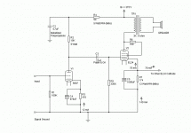
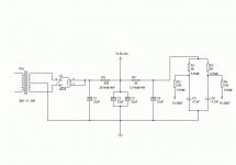
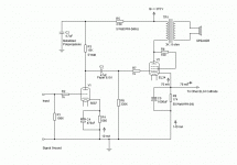
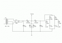
I've been playing around with a SE EL34 design that I plan on building but I thought that I would post the design for the amp and see what the more experienced ones think. Please feel free to critique. I'm spending a lot of money on parts so if anyone has any suggestions (reasonable ones) please speak up. This is a simple design and I'm building it to sound like a tube amp. If you listen to your amp using an oscilliscope and don't approve of the design (not that your approval is required) please understand that I want this to sound like a tube amp, not a SS amp. I like smooth. I like second order harmonics, and you are not going to change my mind. I'm looking for suggestions about biasing points and values. Not topologies. I don't mean to sound short, but I'm not looking for a 50 post debate on the merits of SE design. Just a few suggestions. Thanks.
G
Attachments
Only a couple of things I can think of- why EL34 in triode? That would bring output power down to about 4-5W.
If you want the sound of a triode, why not use a triode! (unless of course you have lots of NOS EL34s lying around 🙂 )
You should experiment a little as well- try pentode mode and ultralinear if possible.
And I would use a bigger coupling cap- 0.47 or so, just my unscientific experience... better bass.
Also an inductor in the power supply really smooths things out- have you simulated the PSU on PSUD2? I would use an inductor for sure.
Aaah, you've been reading the archives 😀 😀
If you want the sound of a triode, why not use a triode! (unless of course you have lots of NOS EL34s lying around 🙂 )
You should experiment a little as well- try pentode mode and ultralinear if possible.
And I would use a bigger coupling cap- 0.47 or so, just my unscientific experience... better bass.
Also an inductor in the power supply really smooths things out- have you simulated the PSU on PSUD2? I would use an inductor for sure.
I don't mean to sound short, but I'm not looking for a 50 post debate on the merits of SE design.
Aaah, you've been reading the archives 😀 😀
One little point... your amp and PS schematics are contradictory in the 5687-supply area. 😉
Not sure but 10k seems a bit low for a 5687. Will have to check.
Only thing I can recommend is global NFB. Chances are you'll like it better with a flatter frequency response and greater-than-unity damping factor. Change the 5687's cathode resistor to a 390, and place a 100 ohm below it (the cap bypasses just the 390 ohm). Ground one side of the speaker output, and run a resistor from the free end to the top of the 100 ohm resistor. A small cap across the feedback R will help HF performance and/or stability (check with scope, experiment with values). Speaking of stability, a Zobel across the EL34's plate load may be neccesary; experiment.
With NFB you may have too little gain with just a 5687; 6DJ8 will work a little better.
-Oh wait.. triode? Didn't notice that 😛 Have fun then.
Tim
In my last PP EL34 amp, I used a very similar op point (360V B+, 70mA/tube, 6ka-a) and it both sounded great and measured well. My cathode resistor was 210R for both tubes.
Tubecad gives 5.2Wrms, Zo=2.28R, 2H=8.1%
I'd get some chokes for the PS too, at least for the first pi position and use seperate cathode resistors and bypasses.
As you don't want any discussion of design, but just op points, why don't you try them for yourself? You obviously have very strong opinions on what sounds good to you, so the only valid opinion would be yours. What anyone else tells you (unless there's a really gross error) is irrelevant.
You misunderstand Brett. What I was trying to avoid was having the thread jacked. Some people would say use a constant current source there and then someone else would disagree and then the thread would be a million miles from where it started and my posting would have been for nothing. I understand what you mean about the choke in the supply. I built a Zen clone using a 5687 in place of the 6N1P. I used their PSU as a model (with a few value changes) and the amp is as quiet as a mouse. Unfortunately it uses EL84s and has the power of a mouse also. I thought I would build one using EL34s and make a "rat" amp. 5 watts isn't very much power unless you listen to an amp that only puts out about 2 watts. It would not be hard to incorporate a choke in the supply though. Thank you for the suggestion.
G
G
Hi Sch3mat1c,
Thanks for your reply. I really like the sound of a 5687 but I have only tried the tube using the biasing points shown in the schematic. As the circuit is drawn there will be about 130v on the plate with about 12mA through the tube. If you bypass the cathode you end up with a damping factor of about 5 or 6 using a 10K plate load. This is a new computer and I haven't loaded TubeCad yet. I'll play with the numbers tommorrow.
G
One other question, why such massive cathode bypass capacitors? About 1/10th those values would be normal???
*I am thinking straight now* 😉
Ok let me re-evaluate your circuit... 😱
Your OPT isn't 10k, it's 3k:8 on the schematic... 😕
I'm with Brett in that a choke is good for the supply. just 1H would do it (I usually wind my chokes so that sounds like me 😉 ) but more than that is cheap and plentiful so go for it.
OTOH... hmm.. do you need to drop voltage there? Would chokes give too much?
More C after the 1st <choke/resistor> wouldn't hurt, doesn't matter. Just a personal preference. *shrug*
On to the amp..
Shifty: if he's using what's on hand, that's fine.. I have some similarly large caps in Revision 3, just because I wanted to use what's on hand. 🙂
I stick by my earlier assessment of possibly low gain; but that depends on what kind of source you have. I'm used to lower levels I guess.
Damping factor should be maybe 4, IIRC the EL34's Rp.
A shared cathode resistor should've netted you some heat here, I guess crosstalk between channels using such only applies to DHTs.
 The only consequences that I see would be bias differences between the tubes, one channel might be at too high bias while the other too low. This will only make a difference near clipping levels, which may or may not be a problem for you.
HTH a little more 😉
Tim
Ok let me re-evaluate your circuit... 😱
Your OPT isn't 10k, it's 3k:8 on the schematic... 😕
I'm with Brett in that a choke is good for the supply. just 1H would do it (I usually wind my chokes so that sounds like me 😉 ) but more than that is cheap and plentiful so go for it.
OTOH... hmm.. do you need to drop voltage there? Would chokes give too much?
More C after the 1st <choke/resistor> wouldn't hurt, doesn't matter. Just a personal preference. *shrug*
On to the amp..
Shifty: if he's using what's on hand, that's fine.. I have some similarly large caps in Revision 3, just because I wanted to use what's on hand. 🙂
I stick by my earlier assessment of possibly low gain; but that depends on what kind of source you have. I'm used to lower levels I guess.
Damping factor should be maybe 4, IIRC the EL34's Rp.
A shared cathode resistor should've netted you some heat here, I guess crosstalk between channels using such only applies to DHTs.

 The only consequences that I see would be bias differences between the tubes, one channel might be at too high bias while the other too low. This will only make a difference near clipping levels, which may or may not be a problem for you.
HTH a little more 😉
Tim
Hi G,
Even if you give each EL34 it's own cathode resistor. I would get a 50W rated cathode resistor. (Definitely if you want both EL34 on 1 resistor)
And if you are going to get expensive parts. Try the 100uF/160V black gate NH as bypass cap for your output tube. Around $20 a piece, but worth it.
Cheers,
Bas
I also like the 5687 as a driver. Would you consider using fixed bias on the eL34? It's always nice to get rid of a a huge resistor/cap. Unless of course the EL34 does not sound good with fixed bias.
Some of the points that you are making I can't defend, but I point you to this schematic:
http://www.decware.com/zenschm1.pdf
and here is the power supply:
http://www.decware.com/zenscmp1.pdf
I'm looking for about -25 volts at the grid of the EL34s so:
174 x .140 = -24.36 volts at the grid
.140 x 24.36 = 3.41 watts being dissipated by the cathode resistor for the EL34s. A 12 watt resistor should be more than adequate at this position. I also stuck with the same value bypass capacitor value that is used in the Zen amp. I can't claim to understand all that happens in a SE amp when you use one bias resistor and one cap for both output tubes. It sounds fine in the EL84 amp that I built. A 25 watt WW is most definately doable at that position though. Thank you.
Since I'm using the same layout as a Zen I will have to play with the design and figure out a way to get a choke in the power supply. It shouldn't be too hard. I just hope it doesn't cause hum. When I finished the EL84 amp it worked correctly and quietly right from the start. I'm hoping to repeat that with this amp.
Sch3mat1c, I thought that you were reffering to the plate resistor for the 5687 being too small a load for the tube too "work" into. I wasn't reffering to the output transformers, but the plate resistors. I didn't design the input stage (or even adapt it) I found it here:
http://www.diyparadise.com/simplepreamp.html
All I have done is a little bit of math to adapt a 5687 and el34s to a "Zen" topology. I thank you for your impressions and recommendations. I will definately work on getting a choke into the power supply
G
.140 x 24.36 = 3.41 watts being dissipated by the cathode resistor for the EL34s. A 12 watt resistor should be more than adequate at this position. I also stuck with the same value bypass capacitor value that is used in the Zen amp. I can't claim to understand all that happens in a SE amp when you use one bias resistor and one cap for both output tubes. It sounds fine in the EL84 amp that I built. A 25 watt WW is most definately doable at that position though. Thank you
Yes the 12Watt should do...I was just thinking of my own SE 6C41C amp ...where 12 watt is not sufficient.
Cheers,
Bas
G said:And here is the PSU.
Doesn't the rectifier tube need to have its heater powered???
If I want it to work I guess that the heater would need to be powered. Since this is obvious I omitted it from the schematic for the power supply.
G
G
G said:If I want it to work I guess that the heater would need to be powered. Since this is obvious I omitted it from the schematic for the power supply.
G
In the schematic you have posted, the heater for the rectifier tube hasn't been left unconnected, like the other tubes, it has been shorted together and then connected to the cathode.
Ergo, it is not at all obvious that the heater is supposed to be powered.
Hi,
Gavin,
I'd still recommend a choke in the PSU just after the first cap, go for at least 100µF after that and I'd up the filmcap for the 5687 to 10µF as well.
Also, I'd try to loose the cathode decoupling caps on both stages...but that will quite likely need some rdesigning of the entire circuit.
That's just me though...😉
- Status
- Not open for further replies.
- Home
- Amplifiers
- Tubes / Valves
- Recommendations on a simple design?


