I picked up a damaged Perpetuum Ebner Musical 660 over the weekend. Beyond repair, so I disassembled it. It was clean as a whistle inside, which was very nice. Everything was put together with nuts and bolts, very few rivets, high-quality workmanship.

631 by Wigwam Jones, on Flickr
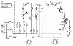
The tube complement was two Siemens ECL82 tubes and one RCA 12AX7A. There were two smallish SE output transformers, and I measured the attached speakers as 3.7 Ohm static resistance, so I presume that they are designed for 4 ohm output.

634 by Wigwam Jones, on Flickr

635 by Wigwam Jones, on Flickr

638 by Wigwam Jones, on Flickr

642 by Wigwam Jones, on Flickr
The medium-sized power transformer had a 'world' voltage adjustment with different taps along the primary side. I measured the 110V setting with 230V HT and 7.5V for heaters, which I presume is too hot. The 125V setting netted me 207V HT and 6.5V for heaters. There is an additional secondary which measures around 15V. However, tracing the wires, I think it was intended to be a part of the primary for higher voltages such as 220 and 240, perhaps put in series with the other primary, so not actually a secondary at all. Not sure.
Anyway, now I have a nice set of tubes and transformers. I'd like to build a small, cheap and cheerful SE amplifier with not-terrible performance and use as many of the original parts as I can.
Before anyone gets worked up, I am quite aware that one cannot build a 'hi-fi' unit with these OPTs. I get it. I am OK with it not being high-fidelity. Good enough is good enough in this case.
So all I really need is a half-way decent circuit to build that uses the two ECL82 tubes and the PT and OPTs.
I've seen a lot of schematics on the web, and they all look vaguely similar except for the 'Super Triode' schematics that use a transistor in the cathode of the triode section, but I don't really understand those. So it looks like something along the lines of a typical SE circuit with maybe 330 Ohm cathode resistance for the pentode and 2.2K cathode resistance for the triode, capacitor bypassed, with minimal NGF, ought to do the trick. I don't think I would need the 12AX7A in this circuit and could use that for some future project.
However, I am far from an expert and would welcome the recommendations of those of you who know far better than I do.
As always, all comments welcomed and appreciated.
631 by Wigwam Jones, on Flickr
The tube complement was two Siemens ECL82 tubes and one RCA 12AX7A. There were two smallish SE output transformers, and I measured the attached speakers as 3.7 Ohm static resistance, so I presume that they are designed for 4 ohm output.
634 by Wigwam Jones, on Flickr
635 by Wigwam Jones, on Flickr
638 by Wigwam Jones, on Flickr
642 by Wigwam Jones, on Flickr
The medium-sized power transformer had a 'world' voltage adjustment with different taps along the primary side. I measured the 110V setting with 230V HT and 7.5V for heaters, which I presume is too hot. The 125V setting netted me 207V HT and 6.5V for heaters. There is an additional secondary which measures around 15V. However, tracing the wires, I think it was intended to be a part of the primary for higher voltages such as 220 and 240, perhaps put in series with the other primary, so not actually a secondary at all. Not sure.
Anyway, now I have a nice set of tubes and transformers. I'd like to build a small, cheap and cheerful SE amplifier with not-terrible performance and use as many of the original parts as I can.
Before anyone gets worked up, I am quite aware that one cannot build a 'hi-fi' unit with these OPTs. I get it. I am OK with it not being high-fidelity. Good enough is good enough in this case.
So all I really need is a half-way decent circuit to build that uses the two ECL82 tubes and the PT and OPTs.
I've seen a lot of schematics on the web, and they all look vaguely similar except for the 'Super Triode' schematics that use a transistor in the cathode of the triode section, but I don't really understand those. So it looks like something along the lines of a typical SE circuit with maybe 330 Ohm cathode resistance for the pentode and 2.2K cathode resistance for the triode, capacitor bypassed, with minimal NGF, ought to do the trick. I don't think I would need the 12AX7A in this circuit and could use that for some future project.
However, I am far from an expert and would welcome the recommendations of those of you who know far better than I do.
As always, all comments welcomed and appreciated.
Full bass extension is not possible, with small O/P "iron". However, the remainder of the audio band should be decent.
Does the unit employ a selenium rectifier? Which of 1/2 wave or bridge rectification is used? A 1/2 wave setup will ground 1 end of the rectifier winding.
Put the 12AX7 away, as you will not need it. It served to make up for tone control circuitry losses. Truly good tone controls require quite complicated circuitry. Forget about them.
Some time ago, I worked with Jeff Yourison on tweaking a Mullard setup for SE 6BM8/ECL82s. Let me do some digging and I'll post again.
Full bass extension is not possible, with small O/P "iron". However, the remainder of the audio band should be decent.
Does the unit employ a selenium rectifier? Which of 1/2 wave or bridge rectification is used? A 1/2 wave setup will ground 1 end of the rectifier winding.
Put the 12AX7 away, as you will not need it. It served to make up for tone control circuitry losses. Truly good tone controls require quite complicated circuitry. Forget about them.
Some time ago, I worked with Jeff Yourison on tweaking a Mullard setup for SE 6BM8/ECL82s. Let me do some digging and I'll post again.
The unit had a Toshiba brand full wave bridge rectifier in it. I kept it but I am hesitant to reuse it.
If you happen to find a nice schematic as you mentioned, I'd be grateful to have it.
I agree that the small output transformers will be unable to reproduce good bass sound. I'm OK with that for this build.
Thanks!
I agree with the assessment that the Toshiba bridge is suspect. A quartet of UF4007s cost very little and, beyond doubt, will perform better.
"Dirt Cheap SE" -- 6BM8 amp
Hi, again,
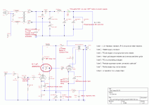
Here is the schematic for a 6BM8 SE amp based on the Mullard ECL82 idea. We added a UL tap with the Edcor output transformer, and modified the feedback with a cap. to ground to produce a cutoff at a couple hundred KHz. A resistor in line with the VC pot at input helps broaden control and saves from overdriving.
This version of the schematic supplies a few additional or corrective notes on components and values.
This design yields an amp that is easy to listen to. It can fill a medium sized room with sound, but it doesn't go super loud with most 84 - 87 dB/W/meter speakers. Nonetheless, I find it most satisfying. YMMV, especially if you try it with more efficient speakers.
--Jeff
Hi, again,
Here is the schematic for a 6BM8 SE amp based on the Mullard ECL82 idea. We added a UL tap with the Edcor output transformer, and modified the feedback with a cap. to ground to produce a cutoff at a couple hundred KHz. A resistor in line with the VC pot at input helps broaden control and saves from overdriving.
This version of the schematic supplies a few additional or corrective notes on components and values.
This design yields an amp that is easy to listen to. It can fill a medium sized room with sound, but it doesn't go super loud with most 84 - 87 dB/W/meter speakers. Nonetheless, I find it most satisfying. YMMV, especially if you try it with more efficient speakers.
--Jeff
Attachments
Last edited:
I recently built a small ECL86 amplifier mainly from early '60 salvaged parts. It does sound better than a 100$ modern China entry level 6p1 amp and also better than the appj pa0901a, both of them have similarly sized small output transformers but their quality is obviously worse than the vintage parts. According to radiomuseum.org the original retail price of PE musical 660 in 1961 was 498 DM: a relatively expensive consumer Hi-Fi with better than average quality. If you use high efficiency small bookshelf units such as Klipsh R-15M, you will barely notice the lacking bass. Dont' be put off by the 4 ohm output impedence. According to my experience ECL86 (and also ECL82, I guess) does work well with higher than recomended output load impedence. I did not reuse any resistor or capacitor from the dismantled vintage radio, modern parts are cheap and more realiable (hint: most switching PSU have 0.1 uF to 0.47uF 275Vac - 400Vdc metalized film capacitors on the input EMI filter. Easy to recover from scrapped devices).
I followed the schematic found in the Philips Technical Library "Rodenhuis - Hi-Fi circuits" book, but I removed the tone circuits. It is very closely related to the more popular Mullard ECL86, and it does have global feedback. You will find the schematic of PE musical 660 at radiomuseum.org. According to this usually accurate source, the ECL82 based player was manufactured 1961-63 and the ECL86 based from 1963 onwards. The schematic is in the ECL86 page but the power transformer is probably the same. You correctly guessed the function of the auxiliary small primary winding on power transformer.
I followed the schematic found in the Philips Technical Library "Rodenhuis - Hi-Fi circuits" book, but I removed the tone circuits. It is very closely related to the more popular Mullard ECL86, and it does have global feedback. You will find the schematic of PE musical 660 at radiomuseum.org. According to this usually accurate source, the ECL82 based player was manufactured 1961-63 and the ECL86 based from 1963 onwards. The schematic is in the ECL86 page but the power transformer is probably the same. You correctly guessed the function of the auxiliary small primary winding on power transformer.
WJ,
As your O/P trafos lack UL taps, full pentode mode "finals", like Mullard used, will have to be employed. Full pentode works best, when g2 B+ is regulated. Do you have an 0A2 on hand?
The small size of the O/P "iron" requires that the "corner" freq. of the high pass filter after the volume control be raised. A 120 Kohm resistor and a 0.033 μF. cap. yield a F3 of approx. 40 Hz.
Hi, Wigwam,
Eli got in touch with me to call attention to this thread. Here is the original Mullard ECL82 SE amp.
I'll follow this with the 6BM8 build we worked on. It sounds very good and is inexpensive.
--Jeff
Thank you! This is quite understandable except for C5. Not clear on what it does?
Hi, again,
Here is the schematic for a 6BM8 SE amp based on the Mullard ECL82 idea. We added a UL tap with the Edcor output transformer, and modified the feedback with a cap. to ground to produce a cutoff at a couple hundred KHz. A resistor in line with the VC pot at input helps broaden control and saves from overdriving.
This version of the schematic supplies a few additional or corrective notes on components and values.
This design yields an amp that is easy to listen to. It can fill a medium sized room with sound, but it doesn't go super loud with most 84 - 87 dB/W/meter speakers. Nonetheless, I find it most satisfying. YMMV, especially if you try it with more efficient speakers.
--Jeff
That looks quite nice, thanks!
I recently built a small ECL86 amplifier mainly from early '60 salvaged parts. It does sound better than a 100$ modern China entry level 6p1 amp and also better than the appj pa0901a, both of them have similarly sized small output transformers but their quality is obviously worse than the vintage parts. According to radiomuseum.org the original retail price of PE musical 660 in 1961 was 498 DM: a relatively expensive consumer Hi-Fi with better than average quality. If you use high efficiency small bookshelf units such as Klipsh R-15M, you will barely notice the lacking bass. Dont' be put off by the 4 ohm output impedence. According to my experience ECL86 (and also ECL82, I guess) does work well with higher than recomended output load impedence. I did not reuse any resistor or capacitor from the dismantled vintage radio, modern parts are cheap and more realiable (hint: most switching PSU have 0.1 uF to 0.47uF 275Vac - 400Vdc metalized film capacitors on the input EMI filter. Easy to recover from scrapped devices).
I followed the schematic found in the Philips Technical Library "Rodenhuis - Hi-Fi circuits" book, but I removed the tone circuits. It is very closely related to the more popular Mullard ECL86, and it does have global feedback. You will find the schematic of PE musical 660 at radiomuseum.org. According to this usually accurate source, the ECL82 based player was manufactured 1961-63 and the ECL86 based from 1963 onwards. The schematic is in the ECL86 page but the power transformer is probably the same. You correctly guessed the function of the auxiliary small primary winding on power transformer.
Thank you! I unfortunately do not have a membership on Radiomuseum.org; applied years ago but never heard back. However, thanks for confirming my guess on the second primary.
WJ,
As your O/P trafos lack UL taps, full pentode mode "finals", like Mullard used, will have to be employed. Full pentode works best, when g2 B+ is regulated. Do you have an 0A2 on hand?
The small size of the O/P "iron" requires that the "corner" freq. of the high pass filter after the volume control be raised. A 120 Kohm resistor and a 0.033 μF. cap. yield a F3 of approx. 40 Hz.
I do have an 0A2, as it happens. Thanks!
Have you tested the tubes? Old pulls of ecl82 and ecl86 tend to be very weak.
I do not have a tube tester. I hope to get one after tax time. I will just have to take a chance for now.
Thank you! This is quite understandable except for C5. Not clear on what it does?
C5 decouples R8, the screen resistor. It functions as a part of the screen power supply source. R8 drops the screen voltage to a value less than the main plate voltage, and an RC network helps filter and stabilize the voltage.
Eli's suggestion to run this in full pentode mode (given your output transformers) means keeping that screen supply in place, where the 6BM8 schem pulls the screen supply from the Ultralinear tap on the output transformer. I also second Eli's suggestion for the input capacitor. That way you can crank up the volume a little more without sending so much bass through the output transformers that they saturate and/or distort.
Last edited:
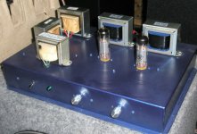
Here's my version of the 6BM8 Dirt Cheap SE, using an inverted commercial cake pan for the chassis.
The OPTs aren't all that big, either. I like to build with dual volume controls to assist with fine tuning balance in my rather unsymmetrical listening areas. Sounds great with a subwoofer, too. Also, I reduced the value of the first input resistors by about half, and have not run into overdriving concers.
Whatever you end up building, I'm sure it will sound great.
--Jeff
Attachments
Last edited:
Thank you very much, great information! I've been plotting evil thoughts all day. Hope to get building on this soon.
- Status
- Not open for further replies.
- Home
- Amplifiers
- Tubes / Valves
- Recommend an ECL82 SE Schematic?