Hello ! I have a sony cdp 337esd and want to change the crystal to a low jitter clock. i have ben searching on ebay and all the clocks i can find have ttl/cmos out, or square, and i want sinewave. Because in the servicemanual the clock waveform is sinus to the cxd1125 chip. Can someone explain to me if i can use these clocks like burson audio ?
It's normal for the output of simple oscillators to be anything but square, such as the one feeding pin 53 ? (from memory) on the CXD1125. Also measuring via the 1k resistor as shown also forms a LPF so that's what is actually measured. Put your scope on the output of the osc and it will be better,
It's squared up properly within the main IC.
So I'm sure the osc you mention is fine as long as the frequency is correct and the outpt is 5 volts (TTL level)
It's squared up properly within the main IC.
So I'm sure the osc you mention is fine as long as the frequency is correct and the outpt is 5 volts (TTL level)
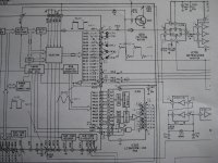
I send the schematic around the chip...Hello ! I have a sony cdp 337esd and want to change the crystal to a low jitter clock. i have ben searching on ebay and all the clocks i can find have ttl/cmos out, or square, and i want sinewave. Because in the servicemanual the clock waveform is sinus to the cxd1125 chip. Can someone explain to me if i can use these clocks like burson audio ?
Attachments
Hi fragglan,
read this, and look at the sort of waveform this simple oscillator produces 🙂
http://focus.ti.com/lit/an/szza043/szza043.pdf
As I say it's normal... and it's not a sine wave oscillator, it's squarewave oscillator of very mediocre performance whose output resembles a distorted sine wave due to the high frequencies involved and the use of cheap logic, and the fact it's shown in the manual measured via the 1k resistor at it's output... but it doesn't matter, because it gets squared up within the main IC.
1k + 'scope probe capacitance at 20mhz forms a very good filter HF filter. That's the main reason it's shown as "sine", because that's the effect caused by putting the probe on there to measure it.
Thank's ! I suppose i can install a lowjitterclock (169344Mhz) 2,3vp-p and remove the 74hc04 iverter and connect emediatly to xTA1 pin53 without the resistor on the cxd1125 . The output 8 from the inverter goes to the cxd1144 xIN pin9 ,can i connect even to this without the resistor?Hi fragglan,
read this, and look at the sort of waveform this simple oscillator produces 🙂
http://focus.ti.com/lit/an/szza043/szza043.pdf
As I say it's normal... and it's not a sine wave oscillator, it's squarewave oscillator of very mediocre performance whose output resembles a distorted sine wave due to the high frequencies involved and the use of cheap logic, and the fact it's shown in the manual measured via the 1k resistor at it's output... but it doesn't matter, because it gets squared up within the main IC.
1k + 'scope probe capacitance at 20mhz forms a very good filter HF filter. That's the main reason it's shown as "sine", because that's the effect caused by putting the probe on there to measure it.
Last edited:
You need to be absolutely sure the frequency is correct.
The manual shows (if I'm making it out correctly) 16mhz as the crystal value and also shows the period as 6.0 ??? or 60 ??? us (microseconds) both of which are incorrect... f=1/t so t=1/f which is 0.0000000625 seconds or 0.06us. That often happens in manuals. But it looks like it's 16 mhz.
Anyway if it is 16.000Mhz then 16.9344 won't do, the CD would run slow.
I'll give it some more thought... rushing at the mo 🙂
Not much more to add really, other than you must be 100% certain that you use a 16mhz oscillator if that is what the crystal is marked as in the player.
Manufacturers do things for a reason, so the 1 k resistor and the 220 ohm from pin 8 are there for some purpose. The only thing I can think of is to reduce any "transient" behavier and glitches.
Also the clock signal on pin 8 is 180 degrees out of phase with that on pin 2... is that of any importance... I suspect not.
I said above it would run slow... I meant fast of course as it's clocking at a higher rate (the disc servos are locked to this clock).
So it's up to you 🙂 what you try. I would say a 'scope was needed to confirm levels in use and to check all is well. You might get it to work but have problems your not aware of... in other words sticking with what's already there might be best.
I found out they calculated like this t=1/f 1/16934400 = 0,000,000,060 (60nS) so this about µ sec is completly wrong. it have to be 16,9344Mhz. But.. if you make the calculation like this f=1/t this happend. 1/0,000,000,060 =16,6666667Mhz. You need a hell of a calculator to get al loooooooong number 59,05139833711 nS and so on... so saying 60nS in the manual can not be used to calculate on,it will miss the frequensy with hundreds of Khz.You need to be absolutely sure the frequency is correct.
The manual shows (if I'm making it out correctly) 16mhz as the crystal value and also shows the period as 6.0 ??? or 60 ??? us (microseconds) both of which are incorrect... f=1/t so t=1/f which is 0.0000000625 seconds or 0.06us. That often happens in manuals. But it looks like it's 16 mhz.
Anyway if it is 16.000Mhz then 16.9344 won't do, the CD would run slow.
I'll give it some more thought... rushing at the mo 🙂
Last edited:
Had time to think more.
Well 16.9344mhz makes sense frequency wise, as it's a multiple of the sample rate although I even looked at the parts list for your player and that states 16.000 mhz in there too.
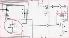
My Micromega shown here uses 33.868 mhz which is divided down to 16.934 as shown here. Very similar circuit.osc really.
So you shouldn't have any major problems getting an external clock to work.
Well 16.9344mhz makes sense frequency wise, as it's a multiple of the sample rate although I even looked at the parts list for your player and that states 16.000 mhz in there too.
My Micromega shown here uses 33.868 mhz which is divided down to 16.934 as shown here. Very similar circuit.osc really.
So you shouldn't have any major problems getting an external clock to work.
Attachments
Thank's for the help! My schematic have really messed up my brain with all this time/period things, but now i take it with a grain of salt. I was even worry for the LRCK that with the calculation was something around 75Khz scary... I waiting fore a scope just for that reason. Thank's again !Had time to think more.
Well 16.9344mhz makes sense frequency wise, as it's a multiple of the sample rate although I even looked at the parts list for your player and that states 16.000 mhz in there too.
My Micromega shown here uses 33.868 mhz which is divided down to 16.934 as shown here. Very similar circuit.osc really.
So you shouldn't have any major problems getting an external clock to work.
- Status
- Not open for further replies.
- Home
- Source & Line
- Digital Source
- Recklocing sine or square ?