and where is over 70% of LCD PANELS produced?
and where is over 80% of COMPUTERS produced?
the list can go on to at least another 50 major products.
its just too overwhelming that they have LIFE CHANGING economy conditions in the last 25years.
cheers
henry
and where is over 80% of COMPUTERS produced?
the list can go on to at least another 50 major products.
its just too overwhelming that they have LIFE CHANGING economy conditions in the last 25years.
cheers
henry
and where is over 70% of LCD PANELS produced?
and where is over 80% of COMPUTERS produced?
the list can go on to at least another 50 major products.
For one reason only - lax working laws, cheap labour. Western economic greed. Not due to skills.

i always want to try reckhorn, i thought its a well made products. Is this common for a sub amp? how about alternatives like the BASH and DAYTON's.
cheers
henry
cheers
henry
BASH amps have a habit of blowing up, often catastrophically. I saw this recently with a friends Cambridge Soundworks speaker set. It sounded fantastic when it worked, but one day there was a bang, some burning, and when we opened it up to look most of the control IC's were fried, and one psu capacitor had exploded.
The replacement caps arrived last week and I decided to measure them both to select the best one to use. One of the caps measures 6640uF and the other measures only 4340uF. Both are NCC KMH 10000uF 100V caps!!!!!!!!!
With long lead times perhaps the amp manufacturer bought the NCC caps from the grey market instead of buying directly from the factory.
Recently I have seen many fakes that look identical to the original. Beware!
Dayton also has crappy caps, but they seem else robustly built and have long warranty.
I have a used Rekhorn A-401 here and it is fine, but hums pretty bad if the other units in the system are ungrounded. The A-401 is ungrounded so it needs to be grounded via the RCA cable. Or possibly by some other means 🙂
I have a used Rekhorn A-401 here and it is fine, but hums pretty bad if the other units in the system are ungrounded. The A-401 is ungrounded so it needs to be grounded via the RCA cable. Or possibly by some other means 🙂
From where you have get the schematic ?
I am looking for the schematic of the model "A-409" - go to
https://www.diyaudio.com/forums/sol...low-pass-subwoofer-schematic.html#post6483165
I am looking for the schematic of the model "A-409" - go to
https://www.diyaudio.com/forums/sol...low-pass-subwoofer-schematic.html#post6483165
Hello. I would be very grateful if someone could offer me the schematic of the A403. Thank you very much.
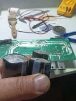
Hello everyone. In my opinion this amplifier is something common, nothing from another world as they speak here. The six 10,000uf capacitors are pirated, not original Rubycon. Mine are already swollen and I have to change them.
The printed circuit is of poor quality and some components are poorly calculated. For example, you have to change the two 680 ohm resistors, from the power supply part for the ICs, for ones of 1k and 2-3W. (R50 and R73). Also the 1k2 resistor R44 must be changed for one of 1k5-1k8 and 3W so that the relay voltage is around 12V. There are models that use 24V relays.
Transistors Q13,Q14, Q24, Q25 and bridge BD1 could use a small heatsink. You also have to redo all the welds because I found many cold welds.
On the plate the filter capacitors say that they are 4700uf/80V. In this case, 6800uf/100V or 8200/100V can be mounted. I don't know if at 10,000uf/100V there are 35x50mm ones to fit into the casing.


Photos made after cleaning and re-soldering the printed circuit. Mount some terminals on the board to be able to test with various resistors without having to disassemble the printed circuit each time.

As I said capacitors are pirates. None measure more than 5200uf and surely they are not for 80V. You can see in the photos how they are swollen.
On the plate the filter capacitors say that they are 4700uf/80V. In this case, 6800uf/100V or 8200/100V can be mounted. I don't know if at 10,000uf/100V there are 35x50mm ones to fit into the casing.
Photos made after cleaning and re-soldering the printed circuit. Mount some terminals on the board to be able to test with various resistors without having to disassemble the printed circuit each time.
As I said capacitors are pirates. None measure more than 5200uf and surely they are not for 80V. You can see in the photos how they are swollen.
Attachments
Hello Rick
greetings is it possible to send me the schematic
my email -andrea.lebon@yahoo.com.
warm regards
Andrew
greetings is it possible to send me the schematic
my email -andrea.lebon@yahoo.com.
warm regards
Andrew
Hi Rick. You can send me the schematic please of the A403? Thank you. livoto1970@yahoo.esWill send to you tomorrow
The schematic is on my work computer.
I have no idea if I have blown the output transistors since I know next to nothing about solid state stuff. I certainly hope I have not.
If you could advise me how to check I would be GRATEFUL!
I am afraid I will not be able to add much to the discussion of how to improve the amps but I would be glad to try changes and let you know what I think fo them.
There does not seem to be much different between the two amps. The 402 did have some kind of filter at the output jacls, a disk ceramic cap from the negative terminal of the output that connects to the chassis. Since it is not on the 403 I plan on leaving it out.
Look for the note tomorrow. I will title it RECKHORN SCHEMATIC.
Thanks,
Hello Cucu
greetings did you manage to fix the amplifier
waiting for the schematic to repair
warm regards
Andrew
greetings did you manage to fix the amplifier
waiting for the schematic to repair
warm regards
Andrew
- Home
- Amplifiers
- Solid State
- Reckhorn A-402 subwoofer amplifier - Warning!!!