Hi everyone
I own a set of Jamo J-121 studio monitors which my dad bought back in the early 80's. I have replaced the electrolytic capacitors with Jantzen Standard Z-cap MKP capacitors in the crossover filter, which gave a significant improvement in the mid and high range (only one speaker so far to compare with). When listening now, the old speaker makes the music sound muffled as if it's in another room, while the restored one is a lot clearer and easier to distinguish voices and instruments, so that's great!
However, the lower frequencies <200 Hz still seem a bit off. I lack proper measurement apparatus, so for now I have to resort to my ears, music, and a tone generator.
Basically if I slowly sweep a sine wave from around 200 Hz and down, there are significant drops at specific frequencies, especially around ~75 Hz, ~63 Hz and ~123 Hz (as my memory serves, I can try and get more accurate "measurements" if needed). At some of these frequencies the volume goes way down, and is higher again once I change the frequency a bit, usually within 1 Hz or so. It also happened before the restoration but at different frequencies, ditto for the other speaker still with old caps.
Is this just a property of the speaker, or do you think I can improve this somehow? The amplifier is a Yamaha RX-465 made for sorround systems, not exactly audiophile but I imagine good enough. The fact that the frequency drops are different depending on speaker/capacitors makes me think the problem is with the speaker itself and not the amplifier.
I have not been able to find the crossover diagram anywhere, if anyone has it it would be greatly appreciated. I hope to drawn my own when I find time, but as I don't have the coil values it might be of limited use.
Questions
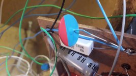
1: There's a flat blue/red component in parallel with the crossover resistors. I suspect a thermistor for tweeter protection. Should I replace it?
2: There are overprotection bulbs/LEDs for mid and hi-range. Do they affect the sound?
3: Could improved damping material change the low volumes so significantly? Currently it seems to just be a bunch of old wool (smells like hair when burnt)
4: Other things worth considering in old speakers?
Thanks!
I own a set of Jamo J-121 studio monitors which my dad bought back in the early 80's. I have replaced the electrolytic capacitors with Jantzen Standard Z-cap MKP capacitors in the crossover filter, which gave a significant improvement in the mid and high range (only one speaker so far to compare with). When listening now, the old speaker makes the music sound muffled as if it's in another room, while the restored one is a lot clearer and easier to distinguish voices and instruments, so that's great!
However, the lower frequencies <200 Hz still seem a bit off. I lack proper measurement apparatus, so for now I have to resort to my ears, music, and a tone generator.
Basically if I slowly sweep a sine wave from around 200 Hz and down, there are significant drops at specific frequencies, especially around ~75 Hz, ~63 Hz and ~123 Hz (as my memory serves, I can try and get more accurate "measurements" if needed). At some of these frequencies the volume goes way down, and is higher again once I change the frequency a bit, usually within 1 Hz or so. It also happened before the restoration but at different frequencies, ditto for the other speaker still with old caps.
Is this just a property of the speaker, or do you think I can improve this somehow? The amplifier is a Yamaha RX-465 made for sorround systems, not exactly audiophile but I imagine good enough. The fact that the frequency drops are different depending on speaker/capacitors makes me think the problem is with the speaker itself and not the amplifier.
I have not been able to find the crossover diagram anywhere, if anyone has it it would be greatly appreciated. I hope to drawn my own when I find time, but as I don't have the coil values it might be of limited use.
Questions
1: There's a flat blue/red component in parallel with the crossover resistors. I suspect a thermistor for tweeter protection. Should I replace it?
2: There are overprotection bulbs/LEDs for mid and hi-range. Do they affect the sound?
3: Could improved damping material change the low volumes so significantly? Currently it seems to just be a bunch of old wool (smells like hair when burnt)
4: Other things worth considering in old speakers?
Thanks!
Attachments


Last edited:
1. If the tweeter sounds fine, I would leave the component in place. Have you measured its resistance? Remember to lift one leg of the component if doing so.
2. Filament lamps can be used for driver protection.They compress the sound when doing their job of protection. Have you actually found filament lamps in there? The indicators on the front panel look like LEDs. To see how those indicators operate you would have to access the circuitry associated with the level adjustment controls.
3. Sheep's wool is one of the best absorbent materials because of the randomness of its fibres. It would be hard to improve on it, but it may be advantageous to experiment with the quantity used.
4. Examine the front and rear suspension (spider) of the bass driver carefully for signs of detachment from the driver basket.
Sounds llike your room. Begin with placement. Subs can help.there are significant drops at specific frequencies, especially around ~75 Hz, ~63 Hz and ~123 Hz
.....
Is this just a property of the speaker, or do you think I can improve this somehow?
1. If the tweeter sounds fine, I would leave the component in place. Have you measured its resistance? Remember to lift one leg of the component if doing so.
2. Filament lamps can be used for driver protection.They compress the sound when doing their job of protection. Have you actually found filament lamps in there? The indicators on the front panel look like LEDs. To see how those indicators operate you would have to access the circuitry associated with the level adjustment controls.
3. Sheep's wool is one of the best absorbent materials because of the randomness of its fibres. It would be hard to improve on it, but it may be advantageous to experiment with the quantity used.
4. Examine the front and rear suspension (spider) of the bass driver carefully for signs of detachment from the driver basket.
1. Tweeter and mids sound OK as I can tell, so I'll leave in the thermistors (PTC fuses?) for now. As far as I understand they do degrade over time, so if I ever decide to change them I hope I can measure a reasonable approximation of the correct value, as it has no markings as far as I can tell! I found a thread with other Jamo speakers having a similar protection: Thermistor removal from crossover rebuild?
2. Yes I'm confident they are actually LEDs. There are no filament lamps, driver protection comes from the thermistors as far as I can tell. They seem to be in parallel with the thermistor as well - When the thermistor increases resistance the current will flow through the LEDs and they light up, indicating the protection, I assume. I take it this won't affect the sound so much, as the thermistor is super low resistance when not warm.
3. Good to hear, I'll leave the wool for now, there's plenty of it as well! Re. experimenting with the amount, is there anything to gain from having less? And what should I listen for?
4. The bass drivers looks like they're in good condition, and I can't identify any obvious problems here. The front suspension is some sort of hard black cardboard(?), and while the glue still looks pretty healthy, I guess there could potentially be some tiny holes letting air through. Nothing visible though. Is there a way to tell from listening if there is a issue?
Sounds llike your room. Begin with placement. Subs can help.
Could be. I'll experiment a bit and try and move it to another room and such.
I also managed to reset the EQ on my amplifier (second hand, it has some room correction utility but uses a mic I don't have) and i now get a fuller, more satisfying sound as well.
Thanks for the help so far!
Last edited:
1. I contributed to that thread. The thermistor in parallel with the 18 ohm resistor has a very low resistance when cold so effectively shorts out the 18 ohm resistor, allowing full signal to pass through. When an overload occurs, the thermistor warms up and increases in resistance. The parallel resistance of the high resistance thermistor and 18 ohm resistor is then sufficiently large to reduce the signal.
3. It is worthwhile experimenting with the amount of wool stuffing. Too much can make the lower midrange sound dull.
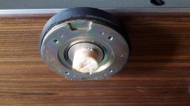
4. The bass driver front suspension is the soft concave section around the circumference as shown in the attached image. You would only have an issue if it were obviously perished or split. Be sure to check the rear suspension for good measure.
3. It is worthwhile experimenting with the amount of wool stuffing. Too much can make the lower midrange sound dull.
4. The bass driver front suspension is the soft concave section around the circumference as shown in the attached image. You would only have an issue if it were obviously perished or split. Be sure to check the rear suspension for good measure.
Attachments
Last edited:
Get REW, room eq wizard, and you can load your room measures to find room modes. You can measures impedance, FR... etc.
Thanks for the help everyone, I feel I'm learning a lot.
Regarding the volume dips at low frequencies, after experimenting a bit, it is definitely some standing waves in the room. Playing a 93 Hz sine wave loudly I can walk around the room and find places with almost complete silence, pretty interesting! I put the measurements into amroc room mode calculator and several of the modes fit more or less what I hear. Good to know, I might work on it in the future.
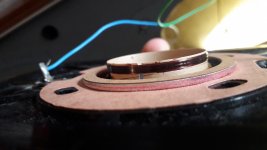
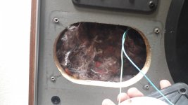
I got a new problem, something slightly more severe: I'm afraid the middle driver is blown on one speaker! (Pictures attached)
No sound was playing from this driver before or after recapping. I removed it from the crossover circuit and tested a bit - There was no connection from one terminal to the other across the driver (using continuity tester in my multimeter). I guess that means the coil inside has burnt over or lost connection somewhere, although I do not see anything from visual inspection.
Regarding the volume dips at low frequencies, after experimenting a bit, it is definitely some standing waves in the room. Playing a 93 Hz sine wave loudly I can walk around the room and find places with almost complete silence, pretty interesting! I put the measurements into amroc room mode calculator and several of the modes fit more or less what I hear. Good to know, I might work on it in the future.
I got a new problem, something slightly more severe: I'm afraid the middle driver is blown on one speaker! (Pictures attached)
No sound was playing from this driver before or after recapping. I removed it from the crossover circuit and tested a bit - There was no connection from one terminal to the other across the driver (using continuity tester in my multimeter). I guess that means the coil inside has burnt over or lost connection somewhere, although I do not see anything from visual inspection.
- This suggests to me the driver is blown, is this correct?
- Is there any hope of fixing this?
- If not fixable - any other suggestions of saving the speaker? I haven't been able to source a replacement without buying a full set of the same speakers.
Attachments


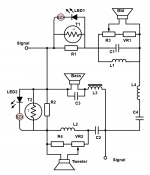
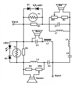
For reference, I've drawn the schematic for the crossover circuit. Maybe it will be useful for someone else later on 🙂
Known values for some components
R1, R2: 18 Ω
R3, R4: 2.2 Ω
VR1, VR2: 8 Ω
T1, T2: <1 Ω
C1: 10 µF
C2: 4.7 µF
C3: 22 µF
C4: 10 µF
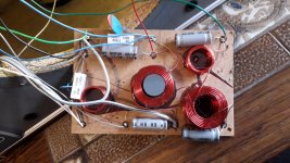
Unfortunately I do not know the values for the coils. I have attached a picture of the physical board as well.
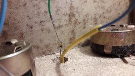
The "BZX" component by the LEDs is one I did not manage to identify, looks like this
Blown mid driver
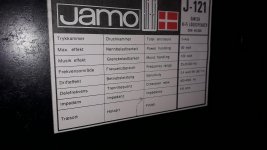
I would still appreciate any suggestions on fixing the mid driver mentioned previously, as it more or less puts an end to my project untill I can fix it. Is it fixable? Would it make sense to buy two new drivers for the mids instead? According to the speaker label, the crossover is "900-4000 Hz", so I could maybe find a replacement, although the rectangular hole poses some challenge for fitting.
Known values for some components
R1, R2: 18 Ω
R3, R4: 2.2 Ω
VR1, VR2: 8 Ω
T1, T2: <1 Ω
C1: 10 µF
C2: 4.7 µF
C3: 22 µF
C4: 10 µF
Unfortunately I do not know the values for the coils. I have attached a picture of the physical board as well.
The "BZX" component by the LEDs is one I did not manage to identify, looks like this
Blown mid driver
I would still appreciate any suggestions on fixing the mid driver mentioned previously, as it more or less puts an end to my project untill I can fix it. Is it fixable? Would it make sense to buy two new drivers for the mids instead? According to the speaker label, the crossover is "900-4000 Hz", so I could maybe find a replacement, although the rectangular hole poses some challenge for fitting.
Attachments
Kogens, I had to remove the inline images as they weren't working, and this changes the flow of your post.
Anyway, the yellow component looks like a zener diode.
Anyway, the yellow component looks like a zener diode.
Thank you Allen, maybe they were too large?
And I agree it does look like a zener diode. I've updated the schematic to include them, although the actual direction of the diodes is guesswork as I didn't disassemble it to test. I'm thinking the LED and zener are opposite of each other, so the LED only lights in case of significant voltage, which would happen when the thermistor/ptc fuse trips.
Also the labels for VR1 and R3 are switched and should now be correct
Attachments
That would be the normal orientation for zeners.
[The images need to be hosted before they are put inline with your post. That includes attaching them just as you have here, which is preferred so they remain with the site.]
[The images need to be hosted before they are put inline with your post. That includes attaching them just as you have here, which is preferred so they remain with the site.]
Alright, I will make sure to attach the pictures.
Peeling back the sticker on the midtone driver reveals it's a Foster D035M13, which I found some details on in the June 1977 edition of Electronics Today from Australia, p. 130:
Electronics Today International, Australia 1977 : Free Download, Borrow, and Streaming : Internet Archive

35 mm, 1.4 inch
Nominal impedance: 8 Ω
Max. power: 40 W,
Resonant freq.: 720 Hz
Rated freq. range: 1500 - 18 000 Hz
Sound press.: 89 dB/W
Flux density: 10 000 Gauss
The rated frequency range strikes me as odd, as the speaker label mentions the crossover as "900 - 4000 Hz" which I assume means the midrange driver gets between 900 Hz and 4000 Hz to play, yet it is only rated down to 1500 Hz?
I found some new old stock of this exact driver on Ebay but only in the US, and with shipping, customs etc. I would pay roughly 100 € total for a pair of these which is a bit more than I expected. Still haven't given up the idea of fixing it first.
I'm also considering finding another (newer) set of midrange drivers instead, i.e. some which are rated down to 900 Hz, although it would be a bit sad to see the originals go. There's also the issue of the oddly shaped hole they for some reason decided to drill for the driver, even though it would have fitted in a circular opening. This would involve a bunch of work to cover properly for a circular driver.
Suggestions are very wecome 🙂
Peeling back the sticker on the midtone driver reveals it's a Foster D035M13, which I found some details on in the June 1977 edition of Electronics Today from Australia, p. 130:
Electronics Today International, Australia 1977 : Free Download, Borrow, and Streaming : Internet Archive
35 mm, 1.4 inch
Nominal impedance: 8 Ω
Max. power: 40 W,
Resonant freq.: 720 Hz
Rated freq. range: 1500 - 18 000 Hz
Sound press.: 89 dB/W
Flux density: 10 000 Gauss
The rated frequency range strikes me as odd, as the speaker label mentions the crossover as "900 - 4000 Hz" which I assume means the midrange driver gets between 900 Hz and 4000 Hz to play, yet it is only rated down to 1500 Hz?
I found some new old stock of this exact driver on Ebay but only in the US, and with shipping, customs etc. I would pay roughly 100 € total for a pair of these which is a bit more than I expected. Still haven't given up the idea of fixing it first.
I'm also considering finding another (newer) set of midrange drivers instead, i.e. some which are rated down to 900 Hz, although it would be a bit sad to see the originals go. There's also the issue of the oddly shaped hole they for some reason decided to drill for the driver, even though it would have fitted in a circular opening. This would involve a bunch of work to cover properly for a circular driver.
Suggestions are very wecome 🙂
Attachments

Last edited:
Just a little update on the speakers: I finally managed to source a replacement midtone driver in Denmark from someone on Vintagehifi.dk • Forsiden and am waiting eagerly for that to arrive.
I also modernized the speaker a bit by replacing the original mounted wire and plug with a new set of terminals. The potentiometers were also cleaned with contact spray to get rid of some scratchiness.


Very pleased with the results so far!
After replacing the midtone I will give them a careful sanding with super fine grit paper, then wax to freshen them up a bit, then they should be good for another 40 years.
I also modernized the speaker a bit by replacing the original mounted wire and plug with a new set of terminals. The potentiometers were also cleaned with contact spray to get rid of some scratchiness.
Very pleased with the results so far!
After replacing the midtone I will give them a careful sanding with super fine grit paper, then wax to freshen them up a bit, then they should be good for another 40 years.
Last edited:
The modernisation is looking good, thanks for the update.
It is most satisfying to give vintage gear such as this a new lease of life. 😎
It is most satisfying to give vintage gear such as this a new lease of life. 😎
@Kogens,
sir, did you happen to have a picture of the tweeters. Of theirs' back side. I need a replacement of mine but the ones on J121 are not originals 🙁
Good job so far on your speakers !!!!
sir, did you happen to have a picture of the tweeters. Of theirs' back side. I need a replacement of mine but the ones on J121 are not originals 🙁
Good job so far on your speakers !!!!
Finally finished! I took them out for a photoshoot in the sun 😀


List of upgrades
Goran, I will take a look when I can and get back to you with the tweeter model number.
List of upgrades
- Electrolytic caps in crossover replaced with Jantzen Standard Z-cap MKP capacitors.
- Potentiometers cleaned and lubed with contact cleaner.
- 3 m old input cable replaced with screw terminals (Monacor ST-925GM)
- One midtone driver was broken and has been replaced.
- Rosewood veneer sandet with grit 240 and given a hardening tabletop oil (Junckers rustik bordpladeolie)*
- Surfaces and cloth panels washed.
Goran, I will take a look when I can and get back to you with the tweeter model number.
Last edited:
- Home
- Loudspeakers
- Multi-Way
- Recapped Jamo J-121 (1979) - further improvements?