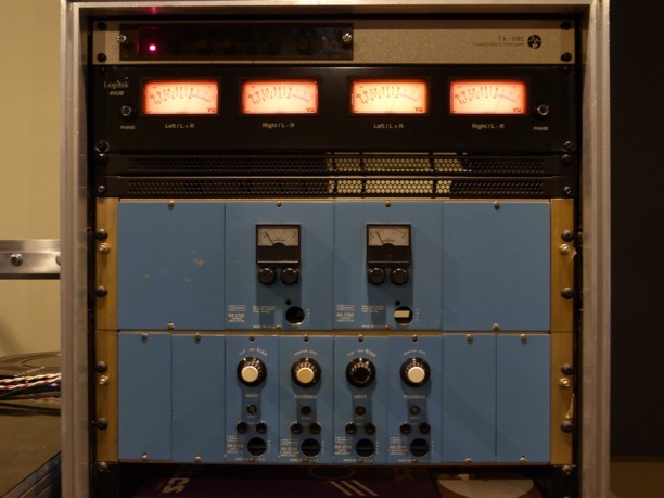
As the title says, I'm recapping the thing, and hard on it. Not a bit of info on the net about this. It's one of these:
For electrolytics, it used sprague little-lytic line, which, is still under production from vishay who acquired sprague.
Well, now that a lot of soldering and desoldering is due, maybe replacing/upgrading it with newer components is the key to a better sound.
Some things that I found that question me a little:
Some Z5U caps in there.
Some electrolytics performing coupling operations.
A nonpolar tantalum 10 uF 15V. (used in the balance trimmer circuit of the power amp, which is a push pull one.
Modules are, as follows:
HF reduction module. (think of a multi-band compressor/limiter). Output goes to input module. Input comes prom program material to be cut.
Input module (with RIAA encoding). Output goes to power amps. Fed from HF module and feedback module.
Power amplifier module (130W / channel). Fed from input module.
Feedback module (which receives info from the cutter-head to equalize the cut). Its output feeds the input module.
Here: Schematics for your enjoyment: lathetrolls [licensed for non-commercial use only]
Ok now, obviously, there are many toasted electros (+30 year old)
So now I am facing a totally renewed market for components. I think I can use some more film caps here and there but lets say for some cases like in the HF reduction equalizer, its coupling cap is a 50 uF, 50V electrolytic, polar cap. Further reading, indicates that for coupling, a cap 10 times its rated capacitance should be used to keep the working voltage/capacitance ratio to a minimum to minimize the fact that it is non-linear by default. http://sound.whsites.net/articles/capacitors.htm
So, questions arise:
¿How do you guys think these amps were designed at the time. ¿Maybe they used a polar electrolytic any time they saw a bias high enough? ¿maybe to save costs?
¿Do you guys thing I'd be better off replacing those electrolytics by films of way less capacitance?
Increasing the low freq capability of a cutter system may lead to disastrous and expensive experiences. Restoring a Westrex 3D cutter head is not trivial and there are very few who can do it.
Keeping the same values is a good idea, changing to film where practical is also a good idea. It is quite doable.
Using a Westrex system usually means you are trying to recreate a certain era of sound. If you wanted a more "audiopile" sound you would not use a Westrex system, you would probably go with a Neumann or Ortofon (if you can find one).
I do recognize that picture as it is one I rebuilt a few years ago. The client was quite pleased with the sound, but did chose to change to a Neumann cutting system when he had the chance.
Cheers and good luck
Alan
I would markup a set of schematics with the (as-built) capacitor values, polarity and dielectric. The flat line on the schematic's symbol is apparently (+) some of the time.
I think old electrolytics have rising ESR past 10kHz. I've been restoring gear with Panasonic FC's and people are happy with them, they do improve the high end having 100kHz rating. For the electrolytics, the only place I would upsize them is on the power supply and bypass. Back in the day they were expensive and designers used the smallest value for economy.
Low frequency response here is important and you don't know if it was part of each stage or a single stage that does the final LF curve.
For the feedback tantalum NP cap, that was used where you need higher freq. response than an (old) electrolytic. I use a NP electrolytic with a film cap in parallel.
Z5U sound horrible, changing to at least COG/NP0 or best film types would be an improvement.
Be very careful with the tuned inductors, get the right tool, do not break the ferrite as I have trying to adjust on old gear. A vaccuum desoldering station is a necessary investment. I do quick checks on the carbon-comp resistors to see if they are off spec.
Looking at the schematics, I dislike the power amp. It is quasi-complementary, uses JFET CC to drive the output stage, this part seems cheaped out. Old gear usually has portions where the designer "blew the budget" and sections where they went cheap. I would think redesigning it or changing it out altogether would greatly improve the unit's sound.
Thanks for the suggestions. Yeah, I have got a desoldering station, temperature controlled. Should be no problem.
So all Z5U are going away.
The power amps, well, I am probably gonna be using a less known version of it, its the 1702A. I have no schematics for it but is a completely new redesign of the units. I got two of these and many of the 1702.
I have heard from the old gurus that a nice maintained westrex cutting system can be as nice as a neumann. Somehow, some attribute the fact that, that was the "way" neumann lathes were marketed and lobbysts did that job when big record companies were choosing between scully or neumann and budget was virtually unlimited. Same happened to some tape recording machines of the era. I.E.: Otari, which was said to be "japanese junk" by the lobbysts; but at the end were workhorses. Not that I want to feel that the westrex is more valuable in a personal manner, as I also have access to neumann lathe electronics. Just a thought.
So, as for the best way to go you guys would feel is better sticking to electrolytics even if they were in coupling positions that could be replaced for modern film caps? Is that "film swapping" procedure a scary thing with more considerations than cost/size?
If thats the way to go, then I am probably gonna use panasonic FC of maybe Elnas.
the Scully Lathe is a beautiful piece of mechanical engineering. The Westrex electronics portion of the system is lame in comparison. The cutter head is very nice. The magical combinations were custom built by those in the industry with lots of chops and money to get it done right. There is no magic answer, and then when you have the equipment, you need someone to drive it, that alone is no mean feat to make it sound excellent in production.
Just replacing caps in these units will make it sound a little smoother, but that's about it.
Stock to stock, the neumann will beat the westrex. after that it becomes how good are you at redesigning a system.
But your best resource is Lathe Trolls, which I know you already know about. Paul et al are very knowledgeable.
Otari tape decks do keep running, til the nickle engineering runs out. But they always sounded really cloudy, maybe it was the 20 al electro caps in each channels audio path! The Otari MTR 90 can be one of the best decks out there, but it needs several thousand dollars of work and a good machinist to make it mechanically do that and then you still have the crappy electronics.
Cheers
Alan
Last edited:
I got under 10 years use out of little-lytics in a hot amp. Very generic part. I don't see Vishay making any long life e-caps now either.
If I'm going to do the job I like the long life caps available now, so I don't outlive the **** things. I had to re-cap one amp four times.
Panasonic FC has endurance as low as 1000 hours in some sizes. I don't see any reason not to use FR which are minimum 2000 or EETED which are minimum 3000 hours, If you can get them. Nichicon also has some reputable long life caps. Newark & digikey stock some long life lines and have the endurance in the selector table. Mouser makes you download the datasheet and read it. Alliedelec didn't stock any long life anything last time I checked.
Best of luck. Glad people are cutting LP's again; maybe the marketers will allow mastering for wide dynamic range instead of for maximum punch in a car in a parking lot duel.
I have seriously narrowed down this search: These are the caps that I am wondering about:
ra1702 amp: C503. Non polar tantalum. I don't know it's function.

ra1703 input: c104, c105.

c120 looks like a decoupling cap or a timing cap to turn on q108 with some lag.
ra1704 feedback: c313 (balance circuit). c304. c318. c315. All big caps, look coupling to me

ra1706 hf reduction amp: c712, c726, c724 and 725.

More exact now!
ra1702 amp: C503. Non polar tantalum. I don't know it's function.
ra1703 input: c104, c105.
c120 looks like a decoupling cap or a timing cap to turn on q108 with some lag.
ra1704 feedback: c313 (balance circuit). c304. c318. c315. All big caps, look coupling to me
ra1706 hf reduction amp: c712, c726, c724 and 725.
More exact now!
It's hard- the schematic is a bit sketchy and has errors. I would take pics of the "as-built" PCB's and markup a schematic with actual values/polarity first.
For the capacitors, I believe:
C503: 10uF 15V NP Tant. I would use 10uF 16V Electrolytic NP.
C503 is for the power amp's negative feedback divider.
C120: Noise filtering for zener voltage regulator CR101 1N978B (51V) and slow ramp up. I'd use 10uF 63V or 100V aluminium electrolytic.
C104: Output coupling capacitor
C105: input amp's negative feedback divider for HF
*I think these two have wrong (schematic) polarity markings? I'm expecting +52VDC power and COM as 0V.
C304: Output coupling capacitor
C318: Output coupling capacitor (if sch error is right, *but why polarity backwards?)
C313: Monitor amp's AC negative feedback
C315: Monitor amp's output coupling capacitor
C712: Output coupling capacitor
C725, C726: LED optocoupler AC bypass
C724: Power supply bypass 9/18kHz filters.
It's strange- a cap is marked "10" and I know it should be a 10uF polarized part, so missing (+) marking and a voltage rating!
Transition frequency for 2N3773
Hi: When I had my studio sales & service business in Nashville, (mid 70's-erly 80's) I maintained a discer cutting system. Scully lathe; mechanical rebuild. Westrex RA 1700 electronics & 3D stereo cutter.
Sold the Westrex manual on Lathe Trolls. It used 2N3550's as output devices in the power amplifier; amp. was rated at 35watts. I see they upgraded to 2N3773 on the 1702. Aside from recapping the unit try finding better output devices. The 3773's have a transition frequency of 0.2 mghz, this is pitiful. Look for something that transitions at 50-100 mghz, at the very least; also check transition freq. of the driver xistrs. It will really clean up the audio quality. Toshiba shold have something suitable. Do not believe the present devices; tho rated @ 150w; actually produce that much output.
Have a Hi Q headphone amp that was a run of the mill design; changed to Toshiba output transistors w trans. freq. 200mghz, night & day difference.
C318: Output coupling capacitor (if sch error is right, *but why polarity backwards?)
C725, C726: LED optocoupler AC bypass
C724: Power supply bypass 9/18kHz filters.
C318 Polarity is indeed, wrong. Circuit is confirming this.
725 AND 726: ¿Should I keep the exact same values or may I change 5 for 4.7uF woth no prob? Same queston goes for the balance circuit cap.
Thanks.
Last edited:
Hi: When I had my studio sales & service business in Nashville, (mid 70's-erly 80's) I maintained a discer cutting system. Scully lathe; mechanical rebuild. Westrex RA 1700 electronics & 3D stereo cutter.
Sold the Westrex manual on Lathe Trolls. It used 2N3550's as output devices in the power amplifier; amp. was rated at 35watts. I see they upgraded to 2N3773 on the 1702. Aside from recapping the unit try finding better output devices. The 3773's have a transition frequency of 0.2 mghz, this is pitiful. Look for something that transitions at 50-100 mghz, at the very least; also check transition freq. of the driver xistrs. It will really clean up the audio quality. Toshiba shold have something suitable. Do not believe the present devices; tho rated @ 150w; actually produce that much output.
Have a Hi Q headphone amp that was a run of the mill design; changed to Toshiba output transistors w trans. freq. 200mghz, night & day difference.
Interesting. Thanks. Have anything specific in mind?
Also, what you mean with the driver xistrs? Which ones?
Last edited:
Driver Transistors
The driver transistors are connected to the 2N3773 output transistors. Just need to check their transition frequency, to make sure they are at least 50mghz.
Sorry I am unable to take time to look this info. up as my wife is in rehab after a 14 day hospital stay.
Bill Wilson
The driver transistors are connected to the 2N3773 output transistors. Just need to check their transition frequency, to make sure they are at least 50mghz.
Sorry I am unable to take time to look this info. up as my wife is in rehab after a 14 day hospital stay.
Bill Wilson
C318 Polarity is indeed, wrong. Circuit is confirming this.
725 AND 726: ¿Should I keep the exact same values or may I change 5 for 4.7uF woth no prob? Same queston goes for the balance circuit cap.
C725 (old 10uF), C726 (old 5uF) LED opto-coupler AC bypass
5uF old -> 4.7uF 25V (6% smaller); 10uF old -> 10uF 25V new electrolytic I think OK subs.
C503: 10uF 15V NP Tant. I would use 10uF 16V Electrolytic NP with film cap 0.1uF in parallel.
For the power amplifier, it's odd in that driver JFET's seem to be current-limiting things and so the design is dependent on hFE of the output stage.
I would keep the low hFE 2N3773's. Some datasheets give fT=4MHz; an antique one fT=0.2MHz
If that is what you believe then you can improve the sound by simply replacing every component with something more expensive. Better to start by having a clear idea of what you want to achieve: repair faults, minimise future faults, modify behaviour?barbaroja said:Well, now that a lot of soldering and desoldering is due, maybe replacing/upgrading it with newer components is the key to a better sound.
Fine for local decoupling. Not fine for anything else.Some Z5U caps in there.
Fine if the right value has been chosen, and so the electrolytics do not dominate the LF rolloff.Some electrolytics performing coupling operations.
That is just a decoupler so anything with about the right value will do. Bipolar electrolytic should be fine.A nonpolar tantalum 10 uF 15V. (used in the balance trimmer circuit of the power amp, which is a push pull one.
Using 10 times the value calculated from LF rolloff ensures that the electrolytic does not dominate the LF response, so it has little signal voltage across it so it cannot contribute significant distortion. Electrolytics are not hugely non-linear (unlike some ceramic caps) so they do not need to be avoided, just used properly.So now I am facing a totally renewed market for components. I think I can use some more film caps here and there but lets say for some cases like in the HF reduction equalizer, its coupling cap is a 50 uF, 50V electrolytic, polar cap. Further reading, indicates that for coupling, a cap 10 times its rated capacitance should be used to keep the working voltage/capacitance ratio to a minimum to minimize the fact that it is non-linear by default.
Some may need replacing. Others may be fine. Every time you swap something which does not need replacing you are taking the risk of doing damage without gaining any compensating advantage.Ok now, obviously, there are many toasted electros (+30 year old)
Only if you are willing to completely redesign the LF response. I suspect you are not in a position to do that, because if you were you would not need to ask us any questions.¿Do you guys thing I'd be better off replacing those electrolytics by films of way less capacitance?
- Status
- This old topic is closed. If you want to reopen this topic, contact a moderator using the "Report Post" button.
- Home
- Amplifiers
- Solid State
- Recap for Westrex 1700 lathe cutter amps