I recommend you test with no load, especially if bases of Q10 and Q11 are still shorted togther. The large crossover region can lead to oscillation in the dead done. If no-load seems to help but amp still oscillates, try disabling the Zobel network, eg. lift one end of R3.
Large DC at the output usually is due to a blown transistor or a problem with global feedback biasing. A technique that often helps is to disconnect the output stages and take the feedback from the driver stage; in your amp you could sever drive at Q10 emitter and Q11 collector. Bias feedback is still present via the junction of CR19 and CR20. Front end operates independently of outputs and should be easier to troubleshoot. Also, there's less chance of damage to outputs.
BTW, what is the amplitude and oscillation frequency showing on your scope?
Thanks.
Last edited:
This amplifier has no decoupling capacitors on its supply rails. The frequency compensation method is sensitive to differences in supply voltage. This is a recipe for oscillation.
Try adding local decoupling capacitors. The main filter capacitors may be in need of replacement.
Ed
Try adding local decoupling capacitors. The main filter capacitors may be in need of replacement.
Ed

You can find the voltage across any resistor using Ohm's law U=I*R
U =Volts
I = milliampere
R=kiloohms
🙂
U =Volts
I = milliampere
R=kiloohms
🙂
Where would I put these exactly and what value should I use? I'm planning to replace the main caps but wanted to fix it first.This amplifier has no decoupling capacitors on its supply rails. The frequency compensation method is sensitive to differences in supply voltage. This is a recipe for oscillation.
Try adding local decoupling capacitors. The main filter capacitors may be in need of replacement.
Ed
Add a 0.1uF 100V ceramic capacitor between the positive rail and ground near Q8. Add another 0.1uF 100V ceramic capacitor between the negative rail and ground near Q9.
Ed
Ed
Finally getting back to this one...
Does it matter where on the board I position the decoupling capacitors? Can I just put them on the molex connector solder points? Above post says to connect them to the ground near Q8 and Q9 respectively but the closest the ground trace gets to there is the middle of the board.
Does it matter where on the board I position the decoupling capacitors? Can I just put them on the molex connector solder points? Above post says to connect them to the ground near Q8 and Q9 respectively but the closest the ground trace gets to there is the middle of the board.
Attachments
Nope, this didn't change anything...Add a 0.1uF 100V ceramic capacitor between the positive rail and ground near Q8. Add another 0.1uF 100V ceramic capacitor between the negative rail and ground near Q9.
Ed
Which ones are those? Ceramics? I rarely if ever see ceramics fail.Change all the compensation capacitors, these tend to go bad on these old pieces
I've never had a seemingly simple amp be this difficult in all the years I've been doing this.
Miller caps and feedback compensation, theres another thread here that suggests semi burned BJTs need to be replaced
I'd replaced transistors already, with original part numbers. Should I just replace all the ceramic caps too? Though I've never had them fail before.
I am finding out that diagnosing problems over the Internet is hard.
Check the resistors around the output transistors. Given that both channels are oscillating, I suspect that the main filter capacitors have developed high ESR.
I too have never seen a ceramic capacitor fail.
Ed
Check the resistors around the output transistors. Given that both channels are oscillating, I suspect that the main filter capacitors have developed high ESR.
I too have never seen a ceramic capacitor fail.
Ed
Definitely hard to diagnose over the internet.
If the issue was an emitter resistor I'd have caught it myself before having to ask for help.
The main caps seem to check out with my meters. And I've never had main caps cause this kind of issue. In my decade of doing this full time. But if somehow something is wrong with them, that would explain why both channels have the exact same issue.
I suppose the possibilities are the following:
-The exact same weird thing has failed in both channels
-The design is so sensitive to parts changes that even parts of the same number were different enough to throw it out of wack
-Something is wrong with the main caps or something common to both channels
The first one seems highly unlikely.
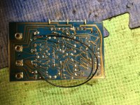
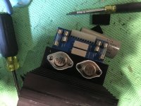
What are all those components around the output transistors marked Fxxx? Are they fuses or ferrite beads? If they are ferrite beads, I'd say that the designer had to struggle to make this thing stable. Perhaps new modern transistors may not be exactly compatible with older ones with lower gain. Did you actually measure the old transistors you replaced? Which ones were faulty?
They are fuses. Oddball sizes that cost me way more than normal sizes too...
Another tech had made a mess in here before, so it is unclear what exactly happened. Some fuses were bypassed.
I might have a good set of the original output transistors I could swap back in to see if that changes anything.
Another tech had made a mess in here before, so it is unclear what exactly happened. Some fuses were bypassed.
I might have a good set of the original output transistors I could swap back in to see if that changes anything.
What are all those components around the output transistors marked Fxxx? Are they fuses or ferrite beads? If they are ferrite beads, I'd say that the designer had to struggle to make this thing stable.
Do you have a parts list identifying the Fxxx types? Are you certain they are aren't ferrite beads as @kapitiaudio asks?
On the chance that they are ferrite beads, I'm going to offer some speculation.
Beads are often used in the base leads to prevent oscillation and are modeled as lossy inductors; many designs use "base stopper" resistors as anti-oscillation measures.
On the other hand, beads in the collectors or emitters make me suspicious. Designers often prescribe low inductance bypass caps near the power transistor collectors and ferrite beads are at odds with bypass wisdom. If you are trying desperation experiments, you might try shorting the beads in the collectors and emitters.
I erred in not reviewing all posts from beginning.
Are bases of Q10 and Q11 still shorted together as in post 10? If so, this quite likely a cause of oscillation. With the output devices disabled, the Zobel network is driven from the bias spreader without the current gain normally provided by the output stages. Temporarily disabling the Zobel path may stop the oscillation. Also, if the outputs are disabled, you must test without a load applied.
If you are still seeing excess offset with the above issues addressed, there's likely a problem somewhere in the preceding stages. As a first step, measure output voltage, and base voltages at Q2 and Q3. If any of these voltages are amiss, reporting voltages across R115 and R120, and voltage at Q10 base and Q10 emitter re ground may give insight.
- Home
- Amplifiers
- Solid State
- Rebuilding blown Audio Design 20A Power Amp: I'm Confused