This were exactly my thoughts, especially as the wooden body turned out to be in an acceptable estate. So sad especially about those four screws protruding the braces in front of the speaker. Wasn't there any possbility to install your new speaker adapter board without any visible attachments? How has the original speaker been installed into the body?You just "broke my heart " Fenris a beautiful antique wooden radio case being turned into a practice amp.Why not sell the case to a US antique radio enthusiast I know plenty of them ?
But, as yet said before, each to his own...
Best regards!
That's how it was done originally. Those are splined screws with a decorative flower head. I had to find reproductions that were true to the original - the only difference is that they're not painted black. I figure adding a little black (speaker cloth, knobs) with touches of silver is a better look than the all brown original. I can always paint the screwheads black later.
Here's what I used:
https://www.amazon.com/Screw-Flower-8-32-Nickel-package/dp/B00M3CJB44
Here's what I used:
https://www.amazon.com/Screw-Flower-8-32-Nickel-package/dp/B00M3CJB44
Last edited:
Well, I'm calmed down then, as you didn't alter the body irreversibly 😉. So anyone could reuse it to restore a radio of the same kind to it's original state, if there should come up a requirement to do so.
The screw head colour doesn't matter at all.
Best regards!
The screw head colour doesn't matter at all.
Best regards!
Sorry for the delay in updates, I've had alot of stuff going on in my personal life.
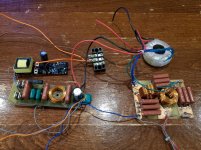
Here's a quick picture of the power supply components (inverter, filter), output transformer, and speaker crossover.
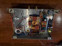
Also a picture of them mounted in place inside the chassis. Everything is mounted with existing holes in the chassis, so it's reversible, although I doubt it ever will be.
Here's a quick picture of the power supply components (inverter, filter), output transformer, and speaker crossover.
Also a picture of them mounted in place inside the chassis. Everything is mounted with existing holes in the chassis, so it's reversible, although I doubt it ever will be.
Attachments
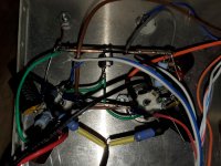
Here's the completed inside before some wire dressing was done. It's not as disorganized as it looks.
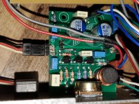
Also a close-up of the socket wiring. This may have been the easiest P2P I've ever done. Almost every component is attached to either the socket and/or a ground bus bar.
Also a close-up of the socket wiring. This may have been the easiest P2P I've ever done. Almost every component is attached to either the socket and/or a ground bus bar.
Attachments
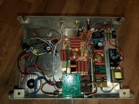
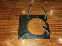
I decided I wanted a fan to keep things cool/reliable. Enermax Marathon fans are very quiet (magnetic bearing), especially if run at lower voltages. I used a RC filter to drop voltage and hopefully reduce any back EMF into the 12v line. It fits on a piece of PCB board that was cut to shape and painted matte black. I also used some rubber vibration reducing mounts to prevent vibrations from causing any noise. The result is that it flows a few CFM, enough to keep temperatures down inside the chassis, but is completely inaudible. It also mounts in existing holes, so again, no permanent modifications.
Attachments
- Home
- Amplifiers
- Tubes / Valves
- Rebuilding an old Philco 89