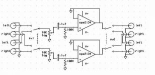
Please use a 100 k or 220 k resistor from the opamp outputs to ground and use a series resistor of 100 Ohm from the opamp outputs to the RCA's/muting circuit. Maybe you can consider to use the muting relay as a shunt to ground to avoid it influencing your precious signal. This, of course, is only possible when you use the 100 Ohm series resistor before the new muting circuit otherwise your opamps won't like it at power up.
An output cap of about 10 uF ( depending on what input impedance your power amp has ) for cancelling DC wouldn't hurt either. It can be omitted if the following power amp has input caps. If you want to use the cap it is best to place it directly after the opamp output and then continue with the above suggested resistors.
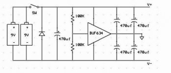
A "real" symmetric power supply would be my first choice, or use the 2 batteries in series for +/- 9V at least. +/- 4.5 V does not leave much headroom does it ? Don't forget to put smaller value ( 4.7 to 100 uF good electrolytics or 0.1 uF MKP or the like ) caps very near the chips power connections for decoupling.
A 10 k volume potentiometer will make your buffer a difficult load for some cdplayers. A 100 k or 50 k would be a better choice IMO.
An output cap of about 10 uF ( depending on what input impedance your power amp has ) for cancelling DC wouldn't hurt either. It can be omitted if the following power amp has input caps. If you want to use the cap it is best to place it directly after the opamp output and then continue with the above suggested resistors.
A "real" symmetric power supply would be my first choice, or use the 2 batteries in series for +/- 9V at least. +/- 4.5 V does not leave much headroom does it ? Don't forget to put smaller value ( 4.7 to 100 uF good electrolytics or 0.1 uF MKP or the like ) caps very near the chips power connections for decoupling.
A 10 k volume potentiometer will make your buffer a difficult load for some cdplayers. A 100 k or 50 k would be a better choice IMO.
00940 said:Is there anything wrong with this ? I need a small switch box and volume control till I can complete a more ambitious tube-based buffer.
As you said it's not really a preamp but a buffer.
For the supply, if you are using just two batteries, you may build a simpler +/- supply using them with nothing else. As it is you could later replace them with two rechargeable 12v batteries.
Carlos
I suggest adding a relay shorting the outputs to ground (after the 100 Ohm resistors) until some seconds after power-up.
Also, I'd use input resistors to ground on all four inputs (47k or something).
Also, I'd use input resistors to ground on all four inputs (47k or something).
Also, I'd use input resistors to ground on all four inputs (47k or something).
Good advice.
moamps said:And disconnect - input and output from ground. 😉
 I did not see that at first glance. Leave the - input connected to the output of the opamp however or your loudspeakers will protest
It is good practice to use an input RC filter to avoid RF creeping in your buffer/poweramp. This filter should be placed in FRONT of the volume potentiometer otherwise you'll have a variable filter as seen in many cheap amps. A 1.2 k resistor and a 1 nF cap will do in most cases.
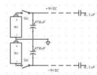
00940 said:Here is the modified version, is this allright now ?
Not really. The joint point between the batteries should go to ground too.
Carlos
It may not seem like much but the LED and bleeder resistors are wasting valuable battery life. For SLA I wouldn't bother removing them, but those 9V get expensive fast.
Well, I've no problem removing the led, it was just cool.
The choice between a voltage divider and the ps below is more tricky. If a battery went to fail, we'd have a severe problem of voltage balance. I know this way is used in the grado ra-1 but most diyers on headfi or headwize would use a setup like in the two posts above. Is it too much of a fear ?
The choice between a voltage divider and the ps below is more tricky. If a battery went to fail, we'd have a severe problem of voltage balance. I know this way is used in the grado ra-1 but most diyers on headfi or headwize would use a setup like in the two posts above. Is it too much of a fear ?
Attachments
00940 said:Well, I've no problem removing the led, it was just cool.
The choice between a voltage divider and the ps below is more tricky. If a battery went to fail, we'd have a severe problem of voltage balance. I know this way is used in the grado ra-1 but most diyers on headfi or headwize would use a setup like in the two posts above. Is it too much of a fear ?
Yes, using a continuously lit LED with 9v batteries will drain them. You may use blinking types.
If you use batteries you may also think on some way to know when they get below a certain voltage. Most modern ICs work down to +/-4.5 or less though, but you will lose some dynamics.
A voltage divider is certainly a good option, but it's far from simple. Now that you put capacitors at the input and output you may go back to it.
The chance of a battery failing is almost as likely as an AC supply failing. A battery should go down slowly, and both at the same time. What you should never do is not putting fresh same type batteries for BOTH units when you change them. Same type and same charge.
In any case DC is a seriosu problem in two cases:
1) If you send DC to an MM or MC cartridge
2) If you send DC to a power amp.
That doesn't mean you should noe prevent that.
Personally I think you should only use blocking capacitors at the power amp input and use low offset chips all along the preamp chain.
Carlos
jean-paul said:The input caps should be 1 uF instead of 0.1 uF.
The input caps should go, as we trust it
that the sources are reasonably free of DC.
Please use JFET-input opamps that are known stable at unity gain.
With a better-controlled power supply you could drop the output caps, but I guess that with batteries this could become a risky business.
The input caps should go, as we trust it
that the sources are reasonably free of DC
It can be dangerous to trust unknown things.
Sure. But the source is known. Either a commercial source with belts-and-braces protection (made in Japan-style), or else a DIY source that is definitely known and where it is your very own responsibility to keep the output free of DC.
And anyway, given the presence of the output coupling caps, the input ones do nothing useful once JFET opamps or opamps with nulled biased current are used.
And anyway, given the presence of the output coupling caps, the input ones do nothing useful once JFET opamps or opamps with nulled biased current are used.
Forgive me, but the 0.1 uF caps for the PSU I hope do go to ground and not in series with DC...?
00940, you might want to consider putting a little bit of gain in to compensate for loss in the pot (depends on the sensitivity of your power amp).
Furthermore, I would heavily recommend getting a couple of opa627's as free samples from TI - they are very nice sounding, and expensive... but who cares when you get them for free?
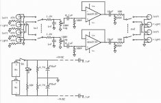
Separating the two channels in distinct chips should give better channel separation.
I don't really think you need those coupling caps - as long as you are careful with changing the batteries, and remember to monitor for DC every time you change something. Newer sources do not output DC, but measure for yourself!
I have the prototype shown here playing, and it is pleasant (with opa627 instead of op37). You might not want the "cheap" class A biasing 15k resistor from output to -, though... and you can make do with 100 ohm output resistor instead of 470.
Your RF input filter is probably a good idea - do keep it.
Despite a small +/- voltage imbalance in the power supply that I haven't got around to fixing yet, DC levels are below 0,1 mV measured with my DMM. My power amp doesn't have a problem with that at all (although it is DC coupled, yes!).
cheers - cdl
Furthermore, I would heavily recommend getting a couple of opa627's as free samples from TI - they are very nice sounding, and expensive... but who cares when you get them for free?
Separating the two channels in distinct chips should give better channel separation.
I don't really think you need those coupling caps - as long as you are careful with changing the batteries, and remember to monitor for DC every time you change something. Newer sources do not output DC, but measure for yourself!
I have the prototype shown here playing, and it is pleasant (with opa627 instead of op37). You might not want the "cheap" class A biasing 15k resistor from output to -, though... and you can make do with 100 ohm output resistor instead of 470.
Your RF input filter is probably a good idea - do keep it.
Despite a small +/- voltage imbalance in the power supply that I haven't got around to fixing yet, DC levels are below 0,1 mV measured with my DMM. My power amp doesn't have a problem with that at all (although it is DC coupled, yes!).
cheers - cdl
I forgot those samples 😱 well, it's repaired, I've a pair of op627ap and a pair of buf634p on their way from TI, no questions asked. I also took a pair of lm317/337 voltage regulators.
With those pieces saved, I could try something slightly better. I'm planning to use the zero distortion power supply. No more problems about batteries. For the rest, I could go for this (pcb perhaps still available from macura) :
Thanks a lot to all of you, your comments helped me a lot.
With those pieces saved, I could try something slightly better. I'm planning to use the zero distortion power supply. No more problems about batteries. For the rest, I could go for this (pcb perhaps still available from macura) :
An externally hosted image should be here but it was not working when we last tested it.
Thanks a lot to all of you, your comments helped me a lot.
- Status
- Not open for further replies.
- Home
- Amplifiers
- Solid State
- Really simple preamp, could someone check it ?