My question: How does a line with low damping differ from a vented box? (In its first octaves.)
Depends on how you compare them. I mean a TL tuned to Fs will be bigger than a vented box tuned to Fs, but because the TL is larger it will have more high gain BW, but its HF will normally be restricted to a deep notch at its 3rd harmonic, so the lower Fs is, the lower in theory it must be XO'd to avoid it.
A TL tuned to the same Fb as a T/S max flat alignment will have more high gain BW, but a much higher F3.
IIRC, GA's TLs are the nearest equivalent to a T/S max flat alignment or what I call a max flat impedance TL alignment since once damped it's ~aperiodic in nature, i.e. its impedance hump is highly damped, so an excellent alignment for when being driven by a high output impedance and/or being XO'd to another driver and was fairly common back when the need for high efficiency dominated speaker design, so now that there's software available that allows the casual DIYer to successfully design such esoteric alignments what was once old is yet new again.
Bottom line, there's many different loading schemes available where each excels in some way or other and it's up to the speaker designer to choose the best one(s) for the app.
GM
but because the TL is larger it will have more high gain BW, but its HF will normally be restricted to a deep notch at its 3rd harmonic, so the lower Fs is, the lower in theory it must be XO'd to avoid it.
This is perhaps the major reason I never warmed up to Karlson boxes. They always seemed to have a big notch in the upper bass/lower midrange.
Last edited:
Guys,
I've been "lurking" and reading this interesting post for a few days. I've also read the Augspurger paper and a bit of the King paper and found both very interesting. After years of hearing much hype I didn't realize that there was some good theory behind TL type speakers.
My question is how they compare to other designs when the variable of line damping is excercised? The undamped examples in Augsperger look essentially like vented boxes with extra resonances added. The damped versions are said to perform similarly to sealed boxes with perhaps better power handling. Proponents think that tapered versions will improve significantly over the "comparable to a sealed box" performance level. Clearly you can trade off the amount of ripple against the amount of bass enhancement. Augspurger aimed for 1dB ripple and achieved a dB or 2 of gain over a sealed system.
My question: How does a line with low damping differ from a vented box? (In its first octaves.)
David
The resultant impedance curve is the easiest and most obvious indicator of the differences between the different loading techniques. Bass reflex designs or the more recent TL's that seem to have been morphed into B/R's have the twin peaks in the resultant impedance curve. Is this the end of the world - not really. Is it optimal - I don't think so - but that's just me. For many years -- about 30 to be exact - I've heard criticisms that B/R's lack the control and linearity of sealed designs when driven hard. And to a great extent, I'd agree with that assessment. Did it stop me from buying and listening to JBL's (one of the biggest proponents of B/R in the history of hifi) since 1979 - heck no. The physics of it suggest that the power response down low with a B/R is more peaky than the other designs. In linear control theory - this high q scenario would be considered less stable. The traditional TL just applies a broader correction to the impedance curve of most drivers. Does this result in a major change? That's a very subjective question. The general consensus is tighter control of the driver with increased drive level and slightly increased deep bass response. Is it worth the added cabinet gymnastics? Again - fairly subjective question.
I ready the OP's linked article. Except for some discrepencies... this is no different than the classic design principals i was writing up in the 70s (and am now advising people to forget)... i still have a "carbon-dated" copy of the original hand written notes. The best written version of this out-of-date methodology is Jon Risch's. None of the background theory in his thou.
a couple points. He talks about a 60% as optimal but it is in relation to a 1/2 wavelength. He then goes on and ignores that completely, setting the line length to wl(fs)/4 times a fudge factor = 0.9. The fudge factor is attributed to the damping slowing down the speed of sound. He tapers the line to reduce standing waves -- the taper (and end correction) being the real reason to have a fudge factor. We now don't have to guess at that, we can calculate it analytically.
He does show another way of achieving the variable line length idea, 1st shown by Karlson... not at the terminus but at the partition. That little tidbit is all i can take away from this paper.
dave
Dave, if you have a published work dating from the 70's that cites the evaluation of an infinite series of the acoustic wave equation producing a summed peak of primary node backwave radiation at 60 degrees (not sure where you're getting 60% from - 60% of what?) phase from the point of excitation - I'll eat my hat. And most definitely, you would deserve major kudos for being nearly 30 years ahead of Mr. Natkaniec. But unless you can produce such proof, you're only engaging in a self back patting exercise here. No one, I and I repeat, no one has produced a paper citing the location of summed primary resonant modes as being anything other than 1/4 wavelength based - including your friend, Martin King. Mr. Natkaniec is the first person I've seen looking into the mathematical principles to actually explain why there's a shift upwards in the frequency of system resonance. Please give credit where credit is due. I'm not suggesting everything in Natkaniec's paper is absolutely correct or useful. Augspurger's testing results suggest that anti resonances have little or no effect overall on system performance so the reference to Karlson's divider may not be very instructive. This does not detract from the central contribution of Natkaniec's paper - that the evaluation of summed back wave energy denoted by application of the acoustic wave equations leads us to an optimal Transmission Line length. Natkaniec may not actually have drawn this conclusion from his approach. I've taken the next logical step and connected the dots. Does that make me absolutely brilliant? Heck no. From my perspective, Natkaniec has done the heavy lifting and in my mind, he deserves all the credit.
Resoanant peaked response 2¢ worth
Resonant peaked woofers are a bad deal. Far better to electronically EQ a rolled off low Q sealed box design. Peaking raises the acoustic output impedance which decreases the ability of the woofer to be flat in any environment. This applies much more to vented, bandpass, or passive radiator designs. Further- small ports as in less than 1/2 the area of the driver will go into power compression and acoustic clipping. Data at hand for an 8" sub with a 2" port shows power compression limiting of the port at 85dBa. Works great at very low volume but not about 85dBa output.
Resonant peaked woofers are a bad deal. Far better to electronically EQ a rolled off low Q sealed box design. Peaking raises the acoustic output impedance which decreases the ability of the woofer to be flat in any environment. This applies much more to vented, bandpass, or passive radiator designs. Further- small ports as in less than 1/2 the area of the driver will go into power compression and acoustic clipping. Data at hand for an 8" sub with a 2" port shows power compression limiting of the port at 85dBa. Works great at very low volume but not about 85dBa output.
(not sure where you're getting 60% from - 60% of what?)
From the paper you linked and supposedly a 1/2 wl. The only thing i could find in that paper that had any relation to this
This lead to the conclusion that an "ideal" transmission line length corresponds to 1.5 times the driver's peak resonant frequency.
No one, I and I repeat, no one has produced a paper citing the location of summed primary resonant modes as being anything other than 1/4 wavelength based
Including from his paper Mr. Natkaniec. Otherwise why would he build his TL to the classic line length.
Augspurger's testing results suggest that anti resonances have little or no effect overall on system performance
You must have read a different paper than the rest of us. The nodes & peaks participate equally in the ripple inherent in a transmission line.
Natkaniec's paper ... an optimal Transmission Line length
He choose quarter wavelength x a fudge factor (which we now know is due to the line taper, which is also responsible for the harmonics shifting upward)
dave
Resonant peaked woofers are a bad deal. Far better to electronically EQ a rolled off low Q sealed box design. Peaking raises the acoustic output impedance which decreases the ability of the woofer to be flat in any environment. This applies much more to vented, bandpass, or passive radiator designs. Further- small ports as in less than 1/2 the area of the driver will go into power compression and acoustic clipping.
I've been thinking, and I'm not sure about this. In fact, I might be swayed to believe that a TL deisgn in a real room just might be a good thing (contrary to my previous point of view, which did not see any advantages). Rooms at LFs are resonant with sparce modes, generally widely spaced. If a TL were done such that it fit its modes in between the rooms modes and they were damped at about the same rate as the room modes, then this would act so as to make the room appear to be larger - modally. This could be a good thing, but there are several "ifs" involved. If I get the chance I'll model this in my room models and see what happens. In all likelihood however, I won't get the chance🙁.
PS - there is no such thing as "acoustic clipping". Ports can compress due to flow, but they can't clip.
I must agree if the TL is tuned for a particular application (room) the TL can perform well.
Experience has shown to get good bass in a room some form of tuning the sub in the room must be completed. Not to many of us are lucky enough to toss a sub in a room and get anything like flat response.
What would you call a sine wave signal which is squished on top with lots of 3rd order harmonics appearing suddenly? Looks soft clipped to me. The port is output is fairly low distortion until it approaches the third order intercept at 85dBa in the example. At 78dBa the distortion is less than 1%, at 82dBa port distortion measured 6%, and at 85dBa distortion showed 10%. This was as loud as the port would play in the example. Increase active woofer drive 10dB only increased port output 0.3dB. Still seems like power compression leads to a form of soft clipping because of the increase in measured odd order distortion.
Hello Freddi,
What's the dish in the pic? RA stuff? 🙂
- Elias
What's the dish in the pic? RA stuff? 🙂
- Elias
An externally hosted image should be here but it was not working when we last tested it.
This is perhaps the major reason I never warmed up to Karlson boxes. They always seemed to have a big notch in the upper bass/lower midrange.
Me neither until Freddy asked me to de-mystify it a bit which at first I was at a loss to do since I was well aware of JK's explanation and couldn't make it 'gell' with its construction, but once I ignored it I could see it for what it was and at that point he sent me PWK's measurement/observation that confirmed it.
The first dip is nothing compared to when the front cavity has finally bottomed out around 500 Hz where some claim it works well XO'd at this point, but for me it needs to be at the first dip to have some overlapping BW to help support the HF driver's low end in this BW where music's greatest dynamics reside. Oh well, different strokes.........
GM
Attachments
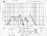
PWK sent me a copy of the graph. fwiw here's ~ ground plane of a Karlson (40sq.in. vent) vs Bill Woods v-vent reflex each with M151 - note the effect of tilting the K so its baffle is upright - its pretty much the same as the reflex up high
An externally hosted image should be here but it was not working when we last tested it.
I think I've stated pretty clearly the important piece of information I found useful from Natkaniec's paper. I've concluded that it's safe to say a pipe length of 1/6 the driver Fs wavelength (pipe frequency being 1.5 times Fs) is optimal for suppressing the driver's energy storage characteristic overall. The upper resonances (above 100 hz) that are objectionable are easily dealt with by stuffing the line. Instead of repeating myself - I think it would be instructive at this stage for you to say why you or Martin refuse to establish an optimum pipe length for any given driver (assuming just a simple pipe without taper or stuffing to make it easy for you) Is it beyond both of your means to do anything other than recommend as Shultz does - a range of pipe lengths from .156 to .2 times the Fs wavelength? Or are you voluntarily avoiding the commitment to establishing a length that optimizes rear wave output - thus maximally suppressing the driver's impedance peak overall?From the paper you linked and supposedly a 1/2 wl. The only thing i could find in that paper that had any relation to this
Including from his paper Mr. Natkaniec. Otherwise why would he build his TL to the classic line length.
You must have read a different paper than the rest of us. The nodes & peaks participate equally in the ripple inherent in a transmission line.
He choose quarter wavelength x a fudge factor (which we now know is due to the line taper, which is also responsible for the harmonics shifting upward)
dave
What's the deal Dave?
I've concluded that it's safe to say a pipe length of 1/6 the driver Fs wavelength (pipe frequency being 1.5 times Fs) is optimal for suppressing the driver's energy storage characteristic overall. ... I think it would be instructive at this stage for you to say why you or Martin refuse to establish an optimum pipe length for any given driver (assuming just a simple pipe without taper or stuffing to make it easy for you)
With the versatility of Martin's model, why limit yourself. The designer can dial in the response he requires with feedback from the FR, phase, impedance, impulse response (he doesn't have to really consider the length except to get a ballpark to start out with and then tune it to hit your target). He can examine the direct response, the terminus response separately.
I'd like to know where you pulled that 1/6 out of Natkaniec paper...
dave
I vaguely remember either Thiel or Small going over this subject.
From what i make of the OP's definition, to use the title of Bailey's article "A Non-Resonant Loudspeaker Enclosure Design". In the article Bailey then goes on and illustrates a 1/4 wave resonant design starting a long standing misunderstanding of what the term TL means.
dave
With the versatility of Martin's model, why limit yourself. The designer can dial in the response he requires with feedback from the FR, phase, impedance, impulse response (he doesn't have to really consider the length except to get a ballpark to start out with and then tune it to hit your target). He can examine the direct response, the terminus response separately.
I'd like to know where you pulled that 1/6 out of Natkaniec paper...
dave
"On the basis of the vector calculus we can observe that when the phase shift is 60° (the tunnel length is equal 1/6 wavelength ), the total radiation is the radiation of the front side of the membrane"
60 degrees (not percent) corresponds to a pipe length of 1/6th the wavelength of interest (in this case the driver's fundamental - Fs) If you've ever examined up close a high performance header piped 426 Hemi or 3.5 liter Ferrari V-12 - you'd notice how different portions of the header have different lengths. The charges that escape the exhaust ports are timed to draw one another in sequence out of the engine. Ever listen to the difference between a headered high performance engine and one that has standard tuning exhaust? The headered version of the same engine can be ear shattering.
This concept of resonance associated with pipe length also applies to the TL. At various points along the line, you will have areas where different wavelengths superimpose or cancel. With the limited band of frequencies in question, it is not that difficult to see where the maximal radiation is along the line. "Cut" the line there - exposing it to the outside world and you maximize output transfer. This is how open ended resonant cavities "resonate". Their resonance is tied most closely to the resonant characteristics of the exciting element - whether they be a person's lips on a trumpet or a reed - or a piston in an engine or ........a woofer perhaps? Augspurger's measurements of an open ended undamped pipe confirm that multiples of the drivers fundamental appear at the output not multiples of the pipe resonant frequency. This heavily contrasts with closed systems that have reflective surfaces at opposite ends. They are more supportive of fixed resonant modes (monotonic) in which the upper harmonics are tied directly to the cavities length.
The real goal of a true transmission line speaker is optimized extraction of the backwave - not very much unlike a header piped scavenger exhausted engine. You may disagree with this design goal - you're certainly free to do so. In that case, we'll just have to agree to disagree. But from my perspective, this approach is fundamental to any attempt at emulating the theoretical infinite baffle.
"On the basis of the vector calculus we can observe that when the phase shift is 60° (the tunnel length is equal 1/6 wavelength ), the total radiation is the radiation of the front side of the membrane"
60 degrees (not percent) corresponds to a pipe length of 1/6th the wavelength of interest (in this case the driver's fundamental - Fs)
That's the part i commented on that wasn't consistent... he does that example for 20 Hz = 2.9m, then when he actually builds it he uses 2.9m for a driver with 30 Hz Fs, saying that is the optimum length.
dave
Performance headers are of equal length, not of different lengths. The premiss of equal length headers is to balance the back pressure experienced by all cylinders, regardless of their location. The noise of a "headered" engine is determined by the rest of the exhaust, if there is any.
I'd say you're using an inaccurate analogy, but you're interpretation of how performance headers function is wrong to begin with.
I'd say you're using an inaccurate analogy, but you're interpretation of how performance headers function is wrong to begin with.
I think it would be instructive at this stage for you to say why you or Martin refuse to establish an optimum pipe length for any given driver (assuming just a simple pipe without taper or stuffing to make it easy for you) Is it beyond both of your means to do anything other than recommend as Shultz does - a range of pipe lengths from .156 to .2 times the Fs wavelength? Or are you voluntarily avoiding the commitment to establishing a length that optimizes rear wave output - thus maximally suppressing the driver's impedance peak overall?
See Table 1 for tapered, straight, or expanding TL length as a function of driver frequency.
http://www.quarter-wave.com/TLs/Alignment_Tables.pdf
Performance headers are of equal length, not of different lengths. The premiss of equal length headers is to balance the back pressure experienced by all cylinders, regardless of their location. The noise of a "headered" engine is determined by the rest of the exhaust, if there is any.
I'd say you're using an inaccurate analogy, but you're interpretation of how performance headers function is wrong to begin with.
Actually performance headers are equal volume of the tube and have nothing to do with length. Common error.🙂
- Status
- Not open for further replies.
- Home
- Loudspeakers
- Multi-Way
- Real Expert or Just Self Proclaimed