Hi folks,
I'm experimenting R-theta's heatsink simulator. It looks very poweful, but I would like to have the seal of approval on my simulation from forum's elders.
DATA:
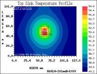
- My chassis design (see it here) provides a 4"x5" heatsink (R-Theta extrusion# 66414...this is actually what I'm planing to buy) for each IRFP244 FET (Aleph2). Therefore, I've set up 25W of heat to dissipate per heatsink (300W overall...12 FETs).
- From IR's datasheets I've found out that the max. junction thermal resistance is 0.83 for the IRFP244
- I've use generic grease for the simluation, Rimp = 0.1 as suggested by the simulator
You can see the output below. Temperature elevation seems not too bad...this is in fact why I'm doubting and asking your advice.
best regards,
Gabriel
I'm experimenting R-theta's heatsink simulator. It looks very poweful, but I would like to have the seal of approval on my simulation from forum's elders.
DATA:
- My chassis design (see it here) provides a 4"x5" heatsink (R-Theta extrusion# 66414...this is actually what I'm planing to buy) for each IRFP244 FET (Aleph2). Therefore, I've set up 25W of heat to dissipate per heatsink (300W overall...12 FETs).
- From IR's datasheets I've found out that the max. junction thermal resistance is 0.83 for the IRFP244
- I've use generic grease for the simluation, Rimp = 0.1 as suggested by the simulator
You can see the output below. Temperature elevation seems not too bad...this is in fact why I'm doubting and asking your advice.
best regards,
Gabriel
Hello,
I am building a Aleph 4 myself. How can you reach the r-theta simulator. I tried something, but I cannot find anything on their website!
I am going to use 5 times a 80mm x 80mm x 150mm heatsink of 0.5 C/W which gives me about 3 * 21 = 63 * 0.50 = 31 C/W ...
Edwin
I am building a Aleph 4 myself. How can you reach the r-theta simulator. I tried something, but I cannot find anything on their website!
I am going to use 5 times a 80mm x 80mm x 150mm heatsink of 0.5 C/W which gives me about 3 * 21 = 63 * 0.50 = 31 C/W ...
Edwin
Fischer...
Did any one look at the Fischer Elektronik SKE 6 400 19" case?
http://www.thel-audioworld.de/bauteile/case/case.htm
Thanks,
Edwin
Did any one look at the Fischer Elektronik SKE 6 400 19" case?
http://www.thel-audioworld.de/bauteile/case/case.htm
Thanks,
Edwin
Edwin, website is www.r-theta.com. You can find the simulator in R-tools section. The simulator only works with netscape and some older IE version.
AudioFreak, having the Rimp increased at 0.75 doesn't change the temperature range. The only error I would see is a unit error. There're talking about "Cin^2/W" for Rimp and you're saying "º/W". What is a "Cin^2/W"?
regards,
Gabriel
AudioFreak, having the Rimp increased at 0.75 doesn't change the temperature range. The only error I would see is a unit error. There're talking about "Cin^2/W" for Rimp and you're saying "º/W". What is a "Cin^2/W"?
regards,
Gabriel
With about a inch square, 0.75 still valid in Cin^2/W.
Since the IRFP244 FET can opererate with a junction temperature up to 150ºC, I guess that 55ºC at the junction is not critical.
Thanks for helping, now I can buy these heatsink with peace of mind.
ciao,
Gabriel
Since the IRFP244 FET can opererate with a junction temperature up to 150ºC, I guess that 55ºC at the junction is not critical.
Thanks for helping, now I can buy these heatsink with peace of mind.
ciao,
Gabriel
Somethings up with the program if it's telling you that you'll end up with a junction temp of 55ºC..........
if i've got my facts correct,
25W per device
each device has it's own heatsink
each heatsink is rated 0.82ºC/W for 100ºC rise .... about 1.134ºC/W for our puposes
and we need a electrical insulator in there too.
So,
Ambient = 25ºC
25 x 1.134 = 28.35C (heatsink)
25 x 0.75 = 18.75ºC (electrical insulator + 2 layers of grease)
25 x 0.83 = 20.75ºC (case to junction)
So, Junction temp should be up around 95ºC for the outter devices and probably about 110ºC for the inner devices....
Now, looking @ the datasheet,
@Tj = 110ºC, irfp244's are rated @ 75W and 215V
Alright, I had misunderstood the graph. This is only simulating the heatsink...55ºC (58ºC at 23ºC ambient), is the temperature at the middle of the heatsink not at the junction of the FET. Still, the temperature of the heatsink itself will be pretty acceptable and this is what I was trying to figure out.
Looking at the written results, the simulator is stating (for 23ºC ambient) 97.4ºC exterior (case) and 118.2ºC interior (junction). Is 118.2ºC too much (acceptable) for the FET (max. 150ºC). I know it will influence the FET's life, but is it critical? What would be the ideal temperature range?
To me, it seems that the FET will be untouchable...almost dangerous.
regards,
Gabriel
That's probably going to work out too high as the internal rows of fets will be in an ambient of about 50ºC and that's assuming that the ambient in the room never exceeds about 25ºC while operating the amps.
assuming best case situation, if all fets had case temp of 100ºC and junction temp of 120ºC,
IRFP244 are rated @ 60W and 210V.
more likely is that the outer rows of fets are close to the above temps and the inner rows are 30ºC hotter. case temp of 130ºC and junction temp of 150ºC,
IRFP244 are rated @ 24W and 200V.
If that is the case, those devices will fail very quickly.
The point is therefore to improve the thermal conductivity between the FET and the heatsink. There's actually two variables: (1) the two layers of grease and (2) the insulator.
1) Digikey sell grease with 0.05ºC/W per 0.001" layer.
http://www.wakefield.com/pdf/Accessories.pdf
2) Digikey also sells mica insulators:
"These precision stamped MICA Insulators provide good thermal conductivity (.009 watts per square inch per
°C per inch in thickness". These are 0.003" thick. Thus 0.33ºCin²/W~0.33ºC/W
This brings down the thermal resistance for the insulation from 0.75 to 0.43; 0.43x25W=10.8ºC which is not really enough; still 85ºC at the case and 100ºC at the junction.
Is there better insulator/grease out there? I really need the best to solve this problem.
Furthermore, one unknown at this moment is the heat dissipation done by the casing and supporting aluminum bars. I'm quite sure this is not neglectible. Combined with a massive venting (for the inner rows of heatsinks) I guess I could give it a try, build the thing and run a real life simulation. This will be the only way to have the real answers.
Once again, what would be the ideal temperature range? Is 100ºC at the junction acceptable?
best regards,
Gabriel
100ºC junction temp is fine.
also, dont count on achieving started thermal resistance of grease + mica + grease as it is highly dependant on mounting pressure which for mosfets is pretty low.
also, dont count on achieving started thermal resistance of grease + mica + grease as it is highly dependant on mounting pressure which for mosfets is pretty low.
Gabster said:The point is therefore to improve the thermal conductivity between the FET and the heatsink. There's actually two variables: (1) the two layers of grease and (2) the insulator.
1) Digikey sell grease with 0.05ºC/W per 0.001" layer.
http://www.wakefield.com/pdf/Accessories.pdf
2) Digikey also sells mica insulators:
"These precision stamped MICA Insulators provide good thermal conductivity (.009 watts per square inch per
°C per inch in thickness". These are 0.003" thick. Thus 0.33ºCin²/W~0.33ºC/W
This brings down the thermal resistance for the insulation from 0.75 to 0.43; 0.43x25W=10.8ºC which is not really enough; still 85ºC at the case and 100ºC at the junction.
Is there better insulator/grease out there? I really need the best to solve this problem.
Furthermore, one unknown at this moment is the heat dissipation done by the casing and supporting aluminum bars. I'm quite sure this is not neglectible. Combined with a massive venting (for the inner rows of heatsinks) I guess I could give it a try, build the thing and run a real life simulation. This will be the only way to have the real answers.
Once again, what would be the ideal temperature range? Is 100ºC at the junction acceptable?
best regards,
Gabriel
Yep,
Fischer Elektronik KAP-218 kapton insulators.... 0.07 C/W ! No need for grease as this is flexible stuff.
See: www.fischerelektronik.de probably other companies make it too.
http://www.fischerelektronik.de/fischer/download_PDF/I-Seiten/I12.pdf
Edwin
kapton is a great insulator but it wont approach that rated thermal resistance given the mounting pressure we use .... also, although it is flexible, it has poor gap filling ability so grease will still be required.
best most practical insulator is mica.
best most practical insulator is mica.
AudioFreak said:kapton is a great insulator but it wont approach that rated thermal resistance given the mounting pressure we use .... also, although it is flexible, it has poor gap filling ability so grease will still be required.
best most practical insulator is mica.
High Performance Kapton-Isolierscheiben
– very low thermal resistance
– optimised thermal conductivity
– best mechanical characteristics
– Polyimide carrier foil with silicone-free
thermal conductive THERMAPHASE
layer, completely coated on both sides
– clean processing, no abrasion of
the coating
– stacked foils do not stick together
– good resistance against cleaning agents
– no cold flow
– low pressure force necessary,
thus particularly suited for spring-fixing
of semiconductors
– cutouts and special versions according
to customers requirements
So LOW pressure force... spring-fixing !
Edwin
that actually sounds pretty good.
i dont particularly like phase change materials but hey it might be worth a shot.
i dont particularly like phase change materials but hey it might be worth a shot.
- Status
- Not open for further replies.
- Home
- Amplifiers
- Pass Labs
- Real "cool" R-Theta heatsink simulation