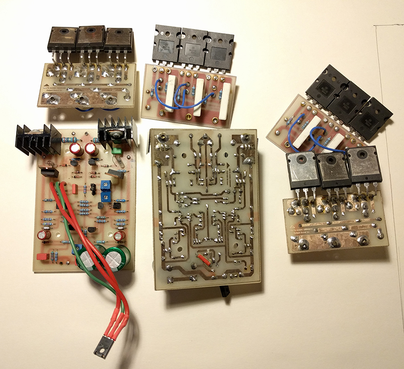
Rewiring older style DIY PCB with crimp type wiring points
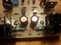
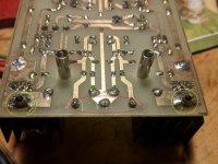
Hi All, I have a second hand set of the original Krell KSA 50 clone boards and I'm trying to re-use them. I haven't gotten very far though because I can't get wire through some of the holes. The connection contact is more of a crimp tube through the PCB. The larger wiring points are left open, but the smaller ones seem to have been crimped on the bottom side of the board and this has fairly effectively closes them off. Pictures attached, let me know if you want a close up.
Do I need to replace these wiring points? If so can someone either tell me how, or help me with some search terms to look for some pointers.
Or is this just a hazard of reusing this type of board and I need to get creative with the wiring, maybe drill some new holes?
Thanks!
Joseph
Last edited:
Those appear to be mounting pins for the heat sinks. Try using a hotter iron, and first add more solder,
before trying to desolder with heavy wick or a tool. Position the board tilted bottom down a little
when desoldering, so the melted solder will flow out the bottom, not into the top of the board.
The other side of the pin has a lot of heat sinking, so you need a lot of heat on the pin.
If that doesn't work, try heating up the pin well (with board bottom facing down), and quickly tap the board sharply
on the bench. Much of the melted solder should fall out of the hole, if you act fast enough.
Last edited:
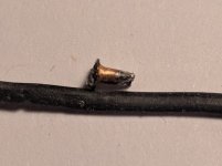
Here is a pin removed
Thanks. These aren't for heatsink mounting, or at least that's not how they are used on this board. Here is one of the pins removed (attached img). See how it is crimped on the bottom. That's the issue, not so much the solder. The crimping also makes them difficult to remove from the board, but it is doable.
Does anyone know what these are called? It would be nice to replace them so I have contact plating through the hole. I just won't crimp the ends this time.
Attachments
That is a funlet. Not sure if they are still made.
You may be able to open up the crimp while heating it up.
Use a pick-shaped tool in the opening, and move it around in a circle.
You may be able to open up the crimp while heating it up.
Use a pick-shaped tool in the opening, and move it around in a circle.
Last edited:
For anyone else wondering how to find these...
They are still available, although from limited sources and they go my many names.
PCB eyelet
Through hole rivet or grommet
PCB through hole solder mount
Be careful not to mistake them for solder in pin sockets for ICs which sometimes go by similar names, but have an internal profile that would make it difficult to use stranded wire.
There a lots of them.
I also use them and buy them here in town, in Swiss. Or you can buy them online from EBAY, if you want to go straight to order them from South East Asia in this Case Bangkok,Thailand. then check this on google..
Amorn embodiment Electro Parts Co., Ltd. Oki branch 24. Or = Natthapong Sales & Service Co.,Ltd. They will cost almost near to nothing and they will send them to you by regular MAILSERVICE.
There are another at least 100 shops.. but if you need only a few send me the size of them diameter and how many you need I will mail them to you in an envelope.. have them here at home..You can PM me your Address..
Two sizes only..
Let me know
They Speak Read and Write English..
Thanks. I just ordered some.
Limited options from the well known electronic supply companies. But once you know what to google, there are plenty of options from Asia.
All brass. Some are advertised as copper, but clearly look like brass. Maybe copper isn't strong enough to hold the form anyway.
Limited options from the well known electronic supply companies. But once you know what to google, there are plenty of options from Asia.
All brass. Some are advertised as copper, but clearly look like brass. Maybe copper isn't strong enough to hold the form anyway.
- Home
- Design & Build
- Construction Tips
- Re using older style DIY PCB