Hi,
i have a set of Alesis 520 Monitors without the amp-pcbs (died sometime ago) so I want to build a very simple XO so I can user them with an external amp.
( Alesis M1 Active 620 & 520 | )
The crossover seems to be 2.8k, 25W tweeter and 50W 5in woofer (RMS? maybe not..)
Can someone link me to a simple design so I can order the parts and do it on a copper board or something?
Ive got this from a XO calc but Im not sure:
2800 Hertz
8 Ohm Tweeter / 4 Ohm Woofer
Parts List
Capacitors
C1 = 5.02 uF
C2 = 10.04 uF
Inductors
L1 = 0.64 mH
L2 = 0.32 mH
If there is an easy to use post or something it would be perfect! Do I just make the 0.63 -> 0.6 and move on?
Thanks
The problem with crossover calculators is that they give a textbook filter curve for a pair of resistors.
Your drivers don't act like resistors, and they have their own frequency response curves, too.
The values from the calculator will give something that produces sound, but I promise it won't be optimal.
Chris
Your drivers don't act like resistors, and they have their own frequency response curves, too.
The values from the calculator will give something that produces sound, but I promise it won't be optimal.
Chris
On-line xo calculators also do not take into account baffle step nor baffle diffraction. without baffle step compensation, your speakers will sound thin / bass weak.
Given the small enclosure / baffle - you will have baffle step to account for in the passive crossover. Baffle step is a more or less 6dB "rise" from very low frequencies to ~ 500 - 1KHz.
Without applying baffle step compensation (usually done by a bigger in-line inductor than you have above - assuming that is your L1) - your speaker will lack bass - sound thin.
A crossover needs to be designed around the varying impedance of the drivers. your quote impedance is "nominal" and usually not the impedance of the drivers (usually ~ 2 ohms less) and these vary due to resonance and inductance. These changing impedances are best handled in a XO simulation tool so you can see the effect on the frequency response.
Your XO above does not handle sensitivity mis-match between tweeter (usually higher output) over woofer. An L-Pad will be needed.
Basically - read the sticky post on "designing crossovers without measurements". In your case, you'll really need to get the driver FRD and ZMA files to do the simulation.
You should also check minimum impedance caused by your XO - so you don't risk frying your amplifiier.
Basically - you could blindly buy the above XO components and try it out. But you'll likely come back with "this is worse than before - how do I fix it"? - well - read what I've said above and do it right the first time.
Sorry if I sound blunt - but just trying to help you avoid mistakes and wasting money on the wrong components.
Your best bet is to ask the members here for someone close who can at least measure the drivers in your enclosure. With those files posted up - one of us can then do a sim to give you a candidate crossover.
Well they are not audiophile speakers and if not usable as they currently are I see no problem with you cobbling together a near enough book XO and playing around.
But you won't be able to cross as low as 2800 with a simple book XO
I'm a big believer in experimentation and the try it and see way of learning how these things work
An alternative might be to get a new small amplifier from Dayton/Parts Express if they still have any small units in stock.
Measure the DCR of the woofer with a multimeter, if its in the range 4.5 to 5.6R then I'd take a chance on it being 8R at 3500Hz and use 3.5kHz as the XO frequency. Put a small resistor in front of the tweeter and use 8R as the impedance.
Nearfield I wouldn't bother with baffle step loss, just use the bass boost on the amplifier to get you through in the short term
Will it be good? Probably not.
But it might be a lot better than having no speakers at all
Can i measute the impedance with the equipment I have?
Ive got a signal generator and a scope. Plus a good multi meter.
I have checked 50ohm loads with it (ham antennas I have built) but nothing less.
Ive got a signal generator and a scope. Plus a good multi meter.
I have checked 50ohm loads with it (ham antennas I have built) but nothing less.
Can i measute the impedance with the equipment I have?
Ive got a signal generator and a scope. Plus a good multi meter.
I have checked 50ohm loads with it (ham antennas I have built) but nothing less.
Technically you can, but it's a little tedious.
Use sig gen to apply sine waves at varying frequencies to the speaker at a known voltage, use multimeter in series with speaker to log current through it, and apply Ohms law to the results. This presumes your multimeter causes no change to voltage or current in the circuit when used in series like this.
Lots of free software can do impedance measurements for you these days too - REW is one, though you do need one or 2 fixed value resistors as well as your cabling etc for that.
I don't know what your technical level is exactly, but if we have a 4 ohm metal woofer and some 8 ohm tweeter, we might have a stab at a simple crossover. HW 2/70 NG - 8 Ohm | VisatonHi,
i have a set of Alesis 520 Monitors without the amp-pcbs (died sometime ago) so I want to build a very simple XO so I can user them with an external amp.
( Alesis M1 Active 620 & 520 | )
The crossover seems to be 2.8k, 25W tweeter and 50W 5in woofer (RMS? maybe not..)
Can someone link me to a simple design so I can order the parts and do it on a copper board or something?
Ive got this from a XO calc but Im not sure:
2800 Hertz
8 Ohm Tweeter / 4 Ohm Woofer
Parts List
Capacitors
C1 = 5.02 uF
C2 = 10.04 uF
Inductors
L1 = 0.64 mH
L2 = 0.32 mH
If there is an easy to use post or something it would be perfect! Do I just make the 0.63 -> 0.6 and move on?
Thanks
You can buy a couple of these puppies at CPC fairly cheaply: https://cpc.farnell.com/visaton/hw2-70ng-8ohm/crossover-2-way-8-ohm/dp/DP33248?mckv=s4gQDtx2s_dc|pcrid|224680571758|kword||match||plid||slid||product|DP33248|pgrid|46864214357|ptaid|pla-464524425811|&CMP=KNC-GUK-CPC-SHOPPING&gclid=EAIaIQobChMI-ZzC4Nm74AIVLrXtCh29PAK8EAQYASABEgLLTvD_BwE
I ran this up the flagpole in Software | Visaton. It's not quite the finished article. But definitely adaptable with an additional 10 uF Capacitor and some tweeter level adjustment. https://www.wilmslowaudio.co.uk/ceramic-resistors-205-p.asp
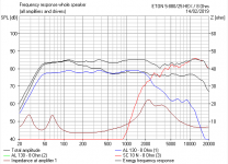
The modelling below. Looks doable to me. 🙂
Attachments

I don't know what your technical level is exactly, but if we have a 4 ohm metal woofer and some 8 ohm tweeter, we might have a stab at a simple crossover. HW 2/70 NG - 8 Ohm | Visaton
You can buy a couple of these puppies at CPC fairly cheaply: https://cpc.farnell.com/visaton/hw2-70ng-8ohm/crossover-2-way-8-ohm/dp/DP33248?mckv=s4gQDtx2s_dc|pcrid|224680571758|kword||match||plid||slid||product|DP33248|pgrid|46864214357|ptaid|pla-464524425811|&CMP=KNC-GUK-CPC-SHOPPING&gclid=EAIaIQobChMI-ZzC4Nm74AIVLrXtCh29PAK8EAQYASABEgLLTvD_BwE
I ran this up the flagpole in Software | Visaton. It's not quite the finished article. But definitely adaptable with an additional 10 uF Capacitor and some tweeter level adjustment. Ceramic Resistors
The modelling below. Looks doable to me. 🙂
Hi,
I just realised that the tweeter is 6ohm (not 8 that I thought) and the woofer 4ohm.
Should I go for the 4ohm version from CPC?
Thanks
The modelling below. Looks doable to me. 🙂
Steve, I have to pull you up on this.
What you've modelled is a totally different set of drivers, in a different enclosure, and suggested that the crossover circuit will work with the drivers the original poster wants to use.
These things don't transfer as well as you might hope.
Chris
Steve, I have to pull you up on this.
What you've modelled is a totally different set of drivers, in a different enclosure, and suggested that the crossover circuit will work with the drivers the original poster wants to use.
These things don't transfer as well as you might hope.
Chris
true and I don't even know if I want to use the 4ohm speakers to be honest, I mixed the number when I though they were 8hm...
all my other speakers are 8ohm.
Speaker impedance has no effect on the sound as far as I am aware, it just effects amplifier performance a bit.
If you aren't going to use the existing drivers in the existing boxes you may as well start from scratch
If you aren't going to use the existing drivers in the existing boxes you may as well start from scratch
Speaker impedance has no effect on the sound as far as I am aware, it just effects amplifier performance a bit.
If you aren't going to use the existing drivers in the existing boxes you may as well start from scratch
For a first-order crossover, doubling (or halving) the impedance will put the rolloff frequency an octave out.
Chris
For a first-order crossover, doubling (or halving) the impedance will put the rolloff frequency an octave out.
Chris
? Only if the XO values haven't been calculated correctly but that wasn't what I said, I said nominal impedance doesn't affect the perceived sound of the speaker
Speaker impedance has no effect on the sound as far as I am aware, it just effects amplifier performance a bit.
If you aren't going to use the existing drivers in the existing boxes you may as well start from scratch
yes I believe you are right. I just had these two taking space and the misses discover them so I thought of using them as back speakers for for the living room until we get something better (approved by the house's central government 😛 )
Im doing a bit of 3d modelling at the moment as I really fancy doing a two way speaker with some sort of horn (tratrix or something more weird) on top. As a person in design the looks are also important 🙂 (please dont judge 🙂 )... visual psychoacoustics heheh
- Status
- Not open for further replies.
- Home
- Loudspeakers
- Multi-Way
- re-use 2 way monitors - very simple crossover