Re: JLH 10 Watt class A amplifier
Hi Diyer,
I have completed the amp with the following config:-
1) 15V x2 Dual Supply with 18V x 2 output voltage.
2) Filter is CLC with 100000uf - 2.5mH - 14700uf
3) Updated JLH version
4) Matched MJ15003 Transistor
5) IQ current is 1.1 and DC offset is < 40mV after warm up.
The power supply is absolutely quiet. The sound is excellent ! Sweet ! and Clear !
But I have one question about the hum. If there is NO input connection on the RCA, there is not hum. If there is an input (JUST RCA cable), there is a low hum (bee) sound. Either one of the cable connected to the amp. There is a small hum sound. You need to place your ear over the speaker to hear this bee.
How can I fix these hum sound?
Thank you very much.
DKO
If you are using a CD player, put a cd in and close the tray as soon as the Cd laser enaged and cd info displayed you should not able to hear the bee.....if this happens I would not worry about it..enjoy..
BTW it seems the norm for CLC is cLC not Clc, so that the inrush current can be easier to handle..
Hope this help..
Chris
BTW it seems the norm for CLC is cLC not Clc, so that the inrush current can be easier to handle..
Hope this help..
Chris
DomKo said:If there is an input (JUST RCA cable), there is a low hum (bee) sound.
How can I fix these hum sound?
DKO
sounds like you have unshielded cable. I put a 10K resistor on my input to reduce stray interference.
Also, I found that using a large decoupling cap on the input transistor helps a lot. Mine (a 1969) is absolutely hum free with a 470uf cap.
BTW, the 1969 version can be easily turned into a dual rail version: you only need to group the feedback capacitor and apply a negative voltage to the "then" ground. I have simulated it and tried it with great success.
the 1996 version seems to be overly complicated. But that's for another discussion.
inrush current
Hi Chris,
I use a Inrush Current thermistor 30 Ohm 5 A for 160VA dual transformers. It work fine.
DKO
Hi Chris,
I use a Inrush Current thermistor 30 Ohm 5 A for 160VA dual transformers. It work fine.
DKO
bias seting
Hello!
Could somebody tell me how I have to set the bias in the original JLH 1969 amp? I know with RV1, but where and what I have to measure?
Thanks!
Hello!
Could somebody tell me how I have to set the bias in the original JLH 1969 amp? I know with RV1, but where and what I have to measure?
Thanks!
Bias
just put an ampermeter in, in serie from your power supply +22vOut or -22vOut. to you amps +22vIn or -22vIn. then you can adjust it.
just put an ampermeter in, in serie from your power supply +22vOut or -22vOut. to you amps +22vIn or -22vIn. then you can adjust it.
Re: Re: Re: JLH 10 Watt class A amplifier
It's not quite that simple.
The output capacitor (and associated 1k resistor) needs to be removed since there will be no dc polarising voltage across it.
The dc blocking capacitor in the feedback network will need to have its polarity reversed since the emitter of Tr4 will sit at about -650mV.
The negative end of the 100uF rail decoupling capacitor should be connected to ground, not the 'new' -ve rail.
Unless you have a *very* quiet supply, the resistor from the 'new' -ve supply rail to the base of Tr4 will need to be split and a capacitor added in a similar manner to that for the positive rail otherwise ripple on the -ve rail will cause audible hum.
millwood said:
BTW, the 1969 version can be easily turned into a dual rail version: you only need to group the feedback capacitor and apply a negative voltage to the "then" ground. I have simulated it and tried it with great success.
It's not quite that simple.
The output capacitor (and associated 1k resistor) needs to be removed since there will be no dc polarising voltage across it.
The dc blocking capacitor in the feedback network will need to have its polarity reversed since the emitter of Tr4 will sit at about -650mV.
The negative end of the 100uF rail decoupling capacitor should be connected to ground, not the 'new' -ve rail.
Unless you have a *very* quiet supply, the resistor from the 'new' -ve supply rail to the base of Tr4 will need to be split and a capacitor added in a similar manner to that for the positive rail otherwise ripple on the -ve rail will cause audible hum.
Re: Re: Re: JLH 10 Watt class A amplifier
I thought about this more last night and here is the shocker: the 1969 can work under dual rails with zero modification. The two "grounding points" are 1) the decoupling cap on the input stage, and 2) the dc blocking cap on the feedback loop. However, the supply rails are just like ground to A/C signals. so for DC blocking purposes, it doesn't really matter where you tie them (well, unless they are incorrectly polarized). So you can either tie them "properly" to the ground, or to the negative supply rail.
simulated it this morning: it worked;
breadboarded it this morning: it worked.
The thing with the jlh is that there really is no DC feedback for the amp so the DC blocking cap in the feedback loop doesn't really add value in the dual rail version. to minimize dc offset, I first chose the decoupling resistor on the input stage to get me within half a volt on the output, and then use the bias trimmer to fine tune the DC operating point. But the DC operating point tends to drift a lot as the amp heats up (+/- 10mv is common in my experiment).
Hope this helps those who wish to turn their single-rail jlh into two-rail jlh.
millwood said:BTW, the 1969 version can be easily turned into a dual rail version:
I thought about this more last night and here is the shocker: the 1969 can work under dual rails with zero modification. The two "grounding points" are 1) the decoupling cap on the input stage, and 2) the dc blocking cap on the feedback loop. However, the supply rails are just like ground to A/C signals. so for DC blocking purposes, it doesn't really matter where you tie them (well, unless they are incorrectly polarized). So you can either tie them "properly" to the ground, or to the negative supply rail.
simulated it this morning: it worked;
breadboarded it this morning: it worked.
The thing with the jlh is that there really is no DC feedback for the amp so the DC blocking cap in the feedback loop doesn't really add value in the dual rail version. to minimize dc offset, I first chose the decoupling resistor on the input stage to get me within half a volt on the output, and then use the bias trimmer to fine tune the DC operating point. But the DC operating point tends to drift a lot as the amp heats up (+/- 10mv is common in my experiment).
Hope this helps those who wish to turn their single-rail jlh into two-rail jlh.
DomKo said:2) Filter is CLC with 100000uf - 2.5mH - 14700uf
I have used much less sophisticated filtering scheme: two 3300uf caps. No hum in my 1969 version at all. However, i did find through experiment that it is instrumental to use a large decoupling cap and reasonably large decoupling resistor on the input stage.
DomKo said:4) Matched MJ15003 Transistor
You don't need to match those output transistors. There is a lengthy debate in the JLH thread, and then later on. I think it is AKSA who pointed out, quite correctly, that the jlh output stage is essentially two SE stage working in tandem. we know you don't need to match transistors in an SE output stage.
Re: bias seting
I used a pair of 0.20ohm emitter resistors for that. Just measure the voltage drop off those resistors.
Alternative, you can just use an amp meter for that. It would be fairly accurate unless you are running the driver / phase splitter hot.
Tyimo said:Could somebody tell me how I have to set the bias in the original JLH 1969 amp? I know with RV1, but where and what I have to measure?
Thanks!
I used a pair of 0.20ohm emitter resistors for that. Just measure the voltage drop off those resistors.
Alternative, you can just use an amp meter for that. It would be fairly accurate unless you are running the driver / phase splitter hot.
DomKo said:Hi Diyer,
But I have one question about the hum. If there is NO input connection on the RCA, there is not hum. If there is an input (JUST RCA cable), there is a low hum (bee) sound. Either one of the cable connected to the amp. There is a small hum sound. You need to place your ear over the speaker to hear this bee.
How can I fix these hum sound?
Thank you very much.
DKO
Hi DKO,
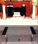
My last JLH-amp (the updated 2003-ESL version) is dead quiet in my home setup.
It's noisy when unconnected cables are present.
However, when several weeks ago I hooked both amps to my son's dual-cd-mixing console (setup for a big party). I HAD A MAYOR hum on one channel when connecting one or two amps to my son's device.
I cured the problem with a simple box which was just a resistor based voltage divider on both channels. Which was needed any way to prevent speaker damage as the output of this console exceeded the sensitivty of my J-Amp.
Two weeks after that I had a similar hum at a test-setup to get some metrics done on my amp.
So, probably, I've might have mixed the wiring of the toroids on both channels. (both main wires are yellow)
I don't mind the noisy part with not connected cables. I'ts not interfering with listning to music (which needs connect cables)🙂
btw this is how my amps look:
An externally hosted image should be here but it was not working when we last tested it.
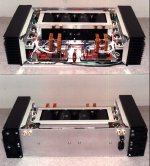
JLH-inside
Here's one inside detail pic taken during testing of the first channel.
Here's one inside detail pic taken during testing of the first channel.
An externally hosted image should be here but it was not working when we last tested it.
btw this is how my amps
Hi Dutch Diy,
Yours is Good Too.
The difference is that your amp is 'SEE THOUGH'.
I try to build it in one case. It is just enough space.
Finally, I add two pairs of cooling fan at the rear side.
I also need to adjust the fan speed to mininize the noise.
Now, the noise of the fan is hearing at about 1 feet. (It's acceptable).
I run the amp with about 12 hrs. The heatsink is kept at about 30 - 40 deg C.
I also test with signal generator from 50Hz to 22000Hz sine wave.
From the oscillograph, there is no visible distortion. I did not have another meter to test.
Enjoy with the music !
- Status
- Not open for further replies.
- Home
- Amplifiers
- Solid State
- Re: JLH 10 Watt class A amplifier