Presented before me I have 2 RE Audio amps to repair... First up is this 800.2
1) I have 2 power FET's shorted... 70N06. Would a IRP3205 or 3215 function here?
2) FDP3672 - 2 are dead short. Anything sub there?
3) What the heck is a KIA78L and a KIA79L at U8 and U9? Little smokey looking there. Mouser not showing anything.
Anything sub in place of this stuff or am I off to order?
1. Yes. 3205 with 47 ohm resistors should work.
2. Use the original.
3. There is a link to the KEC website at the top of the Semiconductor Datasheets page of the tutorial. The number is incomplete. It's likely a KIA78L12 or L15.
2. Use the original.
3. There is a link to the KEC website at the top of the Semiconductor Datasheets page of the tutorial. The number is incomplete. It's likely a KIA78L12 or L15.
1. Yes. 3205 with 47 ohm resistors should work.
2. Use the original.
3. There is a link to the KEC website at the top of the Semiconductor Datasheets page of the tutorial. The number is incomplete. It's likely a KIA78L12 or L15.
I'll swap in 3205's. The gate resistors are out of tolerance anyhow.
I order from mouser the correct other MOSFET's. (I have a 1600.2 to repair also ordering the correct replacements for that amp as well - FDS2552 and IRF1010e says obsolete)
The correct part number is a KIA78L05BP725 at U8 and a KIA79L05BP904 at U9. What are those 5V regulators? And IRF1010 use a 3205 aswell?
ok further examination explains why those two 5V regulators get so hot so fast... The digital driver boards on them were installed wrong.. Theres a nice spot in the middle of both IRS2092s IC's . Unplug the driver boards and neither U8 or U9 get hot. At the input to the board both 5v and -5V look good. The 5v regulators might be OK.
Both IRS2092s changed. Driver boards reinstalled. 5V regulators stay cool. Order to mouser put in... Now I have to wait...
Got the new mosfets in from mouser. Installed them. Since the amp was burnt so good. I just replaced all 4 outputs. Found a few out of tolerance and open resistors on the driver boards. Replaced the outputs with the correct new parts. Installed the driver boards powered amp up. Idle current previously was .3A with new parts went to 1A. About 1 second. A little smoke from driver board resistor! Quickly flipped the Astron off and now 2 of the new outputs are shorted 1 to 2. Dammit. No hot outputs no fire no smoke no damn warning. Hell had the current limiter on less than 2 amps. I love burnt stuff as much as the next guy but geez.
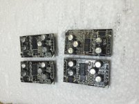
Post a photo of the driver board if you have any questions.
The current limiter won't always protect everything, especially when the secondary supply caps are charged before the output stage is enabled. That's why with some amps, you disable the turn-on delay so that the output stage is enabled before the rail caps charge.
The current limiter won't always protect everything, especially when the secondary supply caps are charged before the output stage is enabled. That's why with some amps, you disable the turn-on delay so that the output stage is enabled before the rail caps charge.

Can I just uninstall the outputs and then install the driver cards to see if there's a problem before I fry more?
The older amps used shunt resistors for the over-current protection circuits. The newer amp use ICs that use the voltage drop across the FET (from drain to source) when the FET is driven 'on'.
The following is a detailed description of amps using the 2092 IC. It should give you enough information to trick the IC into thinking that the FETs are in the circuit.
http://www.irf.com/technical-info/refdesigns/iraudamp5.pdf
Someone else may be able to give more definitive advice. I just haven't seen enough of these to study the ICs.
- Status
- Not open for further replies.
- Home
- General Interest
- Car Audio
- Re Audio XT-800.2 V3 substitute parts?