Hi Everyone...
I have 'cloned' an RD50a (Musicman) amp but I'm having problems.
I had to use a power transformer that is somewhat lower in voltage(s)
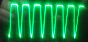
than the schematic. I have 450v to the plates, 225v to pin(s) 4, and +30v to pin(s) 5. I get approx. 40v at the collectors of Q3 & Q4. The waveform going into the bases of Q3 & Q4 is a very good looking sine wave (1khz). The waveform at the collectors is flattened on top at all levels. I am using 35w transformers (output) that spec to the 6L6 tubes. I have to turn the preamp up over half volume to get any sound, and it is very distorted. Any ideas? Is it bias related? or will it even work with the voltages I have available? Any advice will be greatly appreciated.
I have 'cloned' an RD50a (Musicman) amp but I'm having problems.
I had to use a power transformer that is somewhat lower in voltage(s)
than the schematic. I have 450v to the plates, 225v to pin(s) 4, and +30v to pin(s) 5. I get approx. 40v at the collectors of Q3 & Q4. The waveform going into the bases of Q3 & Q4 is a very good looking sine wave (1khz). The waveform at the collectors is flattened on top at all levels. I am using 35w transformers (output) that spec to the 6L6 tubes. I have to turn the preamp up over half volume to get any sound, and it is very distorted. Any ideas? Is it bias related? or will it even work with the voltages I have available? Any advice will be greatly appreciated.
Attachments
You have 450V on the plates, and the grids are at +30V, and the cathodes are at +40V.
That is only -10V of bias (grid to cathode).
You probably have Lots of current in the 6L6GC tubes . . . Right?
Maybe too much.
When the amp is off, and B+ caps are discharged, measure the DCR from one plate to the center tap, and from the other plate to the center tap (some DMMs will autorange, so short the secondary of the output transformer when measuring the primary DCRs).
When you power the amp up again, measure the voltage from the plates to the center tap.
Volts drop / DCR = current.
Plate to cathode volts = 450V - 40V = 410V
410V X plate current = Plate watts dissipated. Needs to be less than 30 Watts.
Or, just measure the voltage across R51 and R54, the 6.8 Ohm resistors from the emitters to ground.
Voltage / 6.8 Ohm = 6L6GC current.
We need to know the current and plate dissipation.
Please let us know.
That may be the first step to troubleshooting the amp.
Thought for later, when you get the amp up and running:
You just might be glad your B+ is only 450V
The original circuit of this Guitar amplifier that puts 585V on the plates, so it grossly exceeds the maximum plate voltage for a 6L6GC (500V max).
With only 450V on the plates, that might make the amp sound different.
But however it sounds, it will do it for a much longer period of time than with 585V on the plates.
Last edited:
check R68, R69. They are supposed to be 75kohm = color code purple/green/orange;
and not 15kohm = color code brown/green/orange;
purple and brown are sometimes indistinguishable and I mixed up 75K and 15K more than once ...
and not 15kohm = color code brown/green/orange;
purple and brown are sometimes indistinguishable and I mixed up 75K and 15K more than once ...
I looked again, and perhaps the screens at only 225V instead of at 290V might be causing the 6L6GC to draw too little current.
Let us know the currents.
There will be very little current in the screen, and more in the plate.
The current in the 6.8 Ohms is the sum of the screen current and plate current.
If changing R60 from 150k to 220k or 270k moves you in the right direction, we may be getting somewhere. You would get a little more upswing on the transistor collectors.
But I like Sorento's clue that R68 and R69 may be only 15k.
Good point Sorento!
Last edited:
Ok, here's what I've got: 0V across 6.8 ohm resistors (R51, R54) There is no voltage drop from B+ (450v) to either plate. Measures exactly the same. Removed R60, no change in 225v - remained constant. Apparently, the tubes are drawing no current at all.
I used two 150k resistors in parallel and measured for 75k - verified. Will changing the +30v (up or down) increase bias? This one has me really stumped. I've been an electronics tech for over 40 years, but no much tube experience. Thanks Guys!
I used two 150k resistors in parallel and measured for 75k - verified. Will changing the +30v (up or down) increase bias? This one has me really stumped. I've been an electronics tech for over 40 years, but no much tube experience. Thanks Guys!
Correction
This is corrected more accurately
This now shows the power supply configuration I put together using the transformer that I had.
This is corrected more accurately
This now shows the power supply configuration I put together using the transformer that I had.
Attachments
Last edited:

Post # 7 schematic is still wrong.
There is a short across C33.
The diodes are connected together, and then to both leads of C33.
Is this supposed to be a doubler supply, with one full voltage output for the output transformer center taps, and 1/2 voltage output for the screens?
Post # 1 had a voltage doubler. But R61 was shorted across.
You have more to correct, in the schematic, and perhaps on the amplifier wiring.
Last edited:
WIth tubes out you may just measure the output from the opamp through the 75k resistor.
Tubes drawing no current at all can have several reasons:
- screen grid pin 4 not connected, a pentode with floating screen cannot conduct
- control grid too negative, or floating, measure with voltmeter directly between cathode pin and grid pin, not just to gnd, what is the actual control grid voltage vs cathode
- 6.8 ohm emitter resistor not connected to gnd is another obvious case for no current
- and don't laugh, I have seen people forget to turn the heaters on ... No glow, no current either ...
Last edited:
The B+ in post #1 was a voltage doubler. That gave 1/2 of B+ voltage for the screens, and full B+ for the plates.
That kind of scheme can be made to work.
Now, in post #9 you are using stacked capacitors again, but not in a voltage doubler.
That means the screens are driven toward ground by 150k and to B+ by 150k.
I do not see how that can work reliably.
The bias supply has 2 diodes in it. I don't know why the second diode is there. This is not a doubler supply, but it is a half wave supply.
We may have to disregard this post... I have found that the output transformers that I ordered, even though cosmetically identical, are completely different. One transformer primary measures 77/68 ohms to center tap, the other measures 119/96 to center tap.
They are either defective factory seconds, or two different impedances. I finally go sound out of the higher measured primary one using EL34 tubes, but distorted at all volume levels. I'll rebuild with reputable transformers and try again... Thanks all for your input.
They are either defective factory seconds, or two different impedances. I finally go sound out of the higher measured primary one using EL34 tubes, but distorted at all volume levels. I'll rebuild with reputable transformers and try again... Thanks all for your input.
- Home
- Amplifiers
- Tubes / Valves
- RD50a Amplifier clone question