Yes. Fancier things are available, but those would be a fine choice.So C3,C9-C11 = electrolytic caps?
All other C's shown in the curcuit i.e wima mkp types?
You've chosen a circuit designed to encourage the use of the valve manufacturer's proprietary valves, as Mullard, MOV, and many others did in the Golden Boom Days of the early 1950s. Transformer manufacturers did the same, and a certain fascination still hangs in the air for pre-War and slightly post-War UTC and Stancor designs in some circles. In the mid-1950s, "UltraLinear" improved this very circuit enough that, with non-proprietary valves, it became the de facto standard. Not modern, or "ideal", but cool.
All good fortune,
Chris

3) I was not aware that JJ made 7027A tubes.
4) From the family of tube curves (7027A); and your B+ voltage after it drops in the primary DCR, the plate voltages, plate current, the g1 bias voltage from the bias supply, and the cathode current.
You also have to estimate the screen current cathode current + screen current = cathode current.
Self bias voltage will lower the plate to cathode voltage, and it will lower the screen to cathode voltage.
I can not read the schematic and parts list.
But here is an example:
Suppose the g1 bias is 20 Volts, and the plate current is 40mA, and the screen current is 5mA.
Start with a self bias voltage of 20V. The cathode current, 40mA + 5 mA = 45mA (0.045A).
20V / 0.045A = 444 Ohms. But we lowered both the plate to cathode voltage and the screen to cathode voltage by the amount of the self bias voltage.
So use a resistor a little lower than 444 Ohms to bring the cathode current back to 45mA (try using 390 Ohm self bias resistors, one for each cathode).
Your amplifier from the RCA circuit may have different cathode current, and different g1 bias voltage; you have to determine that, and then find the appropriate quiescent current on the 7027 family of curves, and calculate the self bias resistor from those conditions.
5) The schematic is unreadable for me (can not read the C numbers, values, etc.).
That includes the coupling caps from the 7199 plate to the 7027 g1 grid circuit.
Do not use electrolytic caps for coupling caps.
6) In Post # 10, artosalo said: "The amount of GNFB is the ratio (in dB) between the two AC signals measured."
20 x Log of the Ratio of AC signal voltages (no negative feedback and with negative feedback). That = the dB of negative feedback.
The advice was to use at least 10dB and no more than 18dB of negative feedback.
Attachments
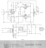
Note that C10 is incorrectly drawn (reversed polarity) in the above. Also, that these "back biased" power supplies are not optimum for several reasons. Electrolytic power supply caps are easily affordable in the needed voltages these days to avoid the "back biasing". Compromises in output valve individual biasing and driver valves' B+ voltage just aren't worth it.
All good fortune,
Chris
All good fortune,
Chris
C10 goes to ground. Why is it incorrectly drawn?Note that C10 is incorrectly drawn (reversed polarity) in the above. Also, that these "back biased" power supplies are not optimum for several reasons. Electrolytic power supply caps are easily affordable in the needed voltages these days to avoid the "back biasing". Compromises in output valve individual biasing and driver valves' B+ voltage just aren't worth it.
All good fortune,
Chris
Yeah I know but are you really sure that C10 must be installed the "wrong way" round. I thought C10 is a simple series connection of the capacitance with C9 ? (Sorry if it should be a "stupid" question ;-) )Polarity is reversed, curved line is conventionally the negative, matters for electrolytics.
ch
Chris is right. The most negative potential in this circuit is the secondary's CT. C10 is in series with C11 and C12, not with C9.
Best regards!
Best regards!
Last edited:
Oh, oh, I am totally lost now. Can someone please send me a simple sketch how to connect C10 ? Many thanks! BRChris is right. The most negative potential in this circuit is the secondary's CT. C10 is in series with C11 and C12, not with C9.
Best regards!
I used back bias and IMO it's so good as any other. In fact, as previous stages current varies only a little, it is a mix of cathode bias plus fixed bias. With the advantage that cathodes can be earthed directly avoiding hum.
It has been largely used in radio, TV, phonographs, ham radio transmitters and amplifiers of the golden age of vacuum tubes.
It has been largely used in radio, TV, phonographs, ham radio transmitters and amplifiers of the golden age of vacuum tubes.
Found this article....I used back bias and IMO it's so good as any other. In fact, as previous stages current varies only a little, it is a mix of cathode bias plus fixed bias. With the advantage that cathodes can be earthed directly avoiding hum.
It has been largely used in radio, TV, phonographs, ham radio transmitters and amplifiers of the golden age of vacuum tubes.
https://www.aikenamps.com/index.php/what-is-back-biasing
got it!Oh, oh, I am totally lost now. Can someone please send me a simple sketch how to connect C10 ? Many thanks! BR
in a maybe later rca design (using 7868 tubes instead of 7027-A) the schematic looks correct here at c10 .
Attachments
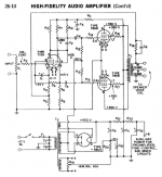
R20 and C10 provide a positive voltage to raise the filament voltages.
The 7199 triode's cathode is very positive.
7199's filament to cathode insulation breaks down with large DC voltage, plus the positive swing with signal.
That insulation breakdown becomes a resistance that is in parallel with the triode's cathode signal load of R8, R9, and R6. Those resistances are the effective cathode resistor of the 7199 concertina phase splitter; as a result the triode plate outputs more signal than the cathode outputs (un-balanced concertina output).
So, the voltage across R20 raises the DC potential to prevent that.
Remember, 7199 are hard to get.
I don't think RCA Engineers were so stupid to ignore this situation. Moreover when published in their own manuals.
Now, as to the practicality of keeping almost all of the output power and essentially the same low distortion levels of the original amplifier . . .
. . . But also using Individual Self Bias for the 7027A tubes (it Is practical).
R20 drops 30V. Instead of using that circuit to raise the filament voltages, use a 2 resistor divider (and bypass cap, C10) off of B+, to get +30V to raise the filament voltage above ground. With R20 out of the circuit (removed and replaced with a jumper wire), we gain 30V of B+ (added 30V to the B+).
And, with the resistor divider off of B+, we have also just 'created' a B+ bleeder resistor.
The original circuit does not have a bleeder resistor.
Use bleeder resistors: Prevent the "Surviving Spouse Syndrome"
Add individual self bias resistors and individual bypass caps.
Now, the voltage drop of the added individual self bias resistors (with that voltage drop) it takes away from the plate & screen voltages to the cathode voltage; but is made up for by the extra 30V of B+.
Or, just keep the original circuit, and get your extremely well matched 6L6GC from eurotubes.com.
The RCA engineers were Very Smart. They included the circuit to raise the filament voltages.
But, as Smart as Dyna was, the Dyna Stereo 70 did not raise the 7199 filament voltage (not smart!).
The filament to cathode insulation degraded over time; I once took a 7199 out of its socket, and measured 100k Ohms between the filament pins to the triode cathode pin; talk about a very un-balanced concertina!
The result . . . lower power out, and higher 2nd order distortion.
Sound Practices issue 10, had an article: "Save those 7199s!" (not my article, but I know the author).
Output tubes better not have hum caused by the filament to cathode interface of un-bypassed cathodes. If they do, they probably need replaced.
Concertina phase splitters are another matter, since the cathodes can not be bypassed, or it is not a phase splitter anymore, 'no-worky'.
Last edited:

I read this thread as it started with a question about the global feedback circuit, and tha lacl of a 16 ohm winding, so I thought I'd add this observation, just for interest.
The OPT has a bandwidth, which means there is actually less feedback for the low bass and high treble. These areas, are of course therefore the regions that need the most feedback, so including the OPT in the GNFB loop is to an extent, self defeating.
The OPT also causes a phase shift, which forces the designer to trade stability for th amount of feedback (as noted on page 1), so it's always a compromise.
But an article written by Thorsten Loech, IIRC, pointed out these two issues, and suggested the obvious solution: to leave the OPT outside ogf the GNFB loop. I actually tried his idea with my single ended amp - perhaps an easier toplogy to try it with, and the result is indeed magnificent 😉.
Almost all the Western Electric amps, which have their cult following, used feedback from the plates, leaving OPT outside of the feedback loop. I heard them all and they do have a certain sound to them (good & bad) and maybe that's one of the sonic reasons for their following, aside from collector fetishism. Many vari-mu audio compressor circuits, typically in PP, in recording industry used feedback before the OPT. One reason is that they wanted floating secondary for balanced output.suggested the obvious solution: to leave the OPT outside ogf the GNFB loop. I actually tried his idea with my single ended amp - perhaps an easier toplogy to try it with, and the result is indeed magnificent 😉.
Interesting!
After the mods, mine just sounded so effortless and open, with plenty of bass too, and a very sweet treble.
I really did it from curiosity, but liked it so much it's been like that every since 😉
I even used a (poly) cap from the plate, even better if one could figure out how to do it via resistors, but perhaps I'd have needed another stage, anyway I was happy with the cap!
The OPT has a bandwidth, which means there is actually less feedback for the low bass and high treble. These areas, are of course therefore the regions that need the most feedback, so including the OPT in the GNFB loop is to an extent, self defeating.
This is exactly the reason why GNFB is taken from the OPT. NFB only reduces the gain of signals that are present and in their proportion. That means if certain frequencies are of a lower amplitude after the OPT then there is less FB to reduce their gain back at the driver. So FB simply works to lower the gain of the stronger part of the audio band compared to the input signal and so flattens the frequency response you get at the output, which is a better representation of the input signal. FB doesn't add anything that isn't there already, it cancels noise and distortion that is created by the amp circuit but not in the original input signal.
- Home
- Amplifiers
- Tubes / Valves
- RCA tube amp (7199 & 7027A) 30W - NFB question